Continue to Site

Welcome to EDAboard.com

Welcome to our site! EDAboard.com is an international Electronics Discussion Forum focused on EDA software, circuits, schematics, books, theory, papers, asic, pld, 8051, DSP, Network, RF, Analog Design, PCB, Service Manuals... and a whole lot more! To participate you need to register. Registration is free. Click here to register now.

Self resonant frequency of MLCC capacitor

Status
Not open for further replies.

kakiitek

Junior Member level 1
Joined
Sep 10, 2020
Messages
17
Helped
0
Reputation
0
Reaction score
0
Trophy points
1
Activity points
173
Hi all,
I am designing a simple step down dc voltage regulator. In the process of selecting output voltage capacitor, i observed that many ceramic capacitor have a self resonant frequency (SLF) of 1000kHz. Some questions below -
1. With the SLF of 1000kHz, we should design the regulator switching frequency well below the 1000kHz. Is that understanding correct?
2. Are there MLCC with SRF way above 1000kHz? So far package like 2016 and 1816 has more or less SRF of 1000kHz.
3. What happens when we choose a switching frequency that is equal to the SRF? Is that effectively a short for the ripple current since there is only the ESR?
4. I have seen schematics with voltage output cap that has the switching frequency very close to the capacitor SRF. The output is stable without any stability issues. Why is that so?
5. On another topic, i have also seen many output voltage capacitor which has an extreme low dc bias spec. Why does the regulation continue to work? For example, a MLCC of 6Vdc used as output capacitor of a Vout of 5.0V. Based on the datasheet, the capacitance is like 10% of its nominal value. Why does it continue to work?

Hope someone could help out here. Many thanks.
Kakiitek
 

MLCC have a wider range of SRF depending on package and capacitance. 10uF 0603 has e.g. 2.5 MHz. SRF is no magical quantity. In a switcher cirquit, it represents a certain amount of series inductance. Switching frequency above SRF is possible, voltage ripple increases of course. Controller stability doesn't specifically depend on SRF respectively ESL, you need to analyze controller phase margin.

My rule of thumb is not to use X5R and X7 capacitors above 50% of rated voltage, the residual capacitance at higher DC can be sufficient for switcher operation but it doesn't seem like a useful choice.
 

    kakiitek

    Points: 2
    Helpful Answer Positive Rating
you often see small caps, 0603, then 0806, then 1206 from 10nF upwards paralleled to create capacitance that has a high SRF

operating a cap at it s SRF is not problem as long as the dissipation is low enough - the tracking to the cap will lower the res freq also ...
 

Hi,

...and mind that a "switching" signal contains overtones.
A 330kHz switching signal will have a lot of 1MHz overtone.

So even a lower switching frequency may cause the capacitor to resonate.

Klaus
 

    kakiitek

    Points: 2
    Helpful Answer Positive Rating
Your filter caps have to suppress not only the switching
frequency but its harmonics, as far out as practical.
Above SRF the capacitor's ESL makes it less, rather
than more effective as frequency rises. Meanwhile
the filter inductor's interwinding capacitance is going
to let higher order harmonics "bypass" the inductor's
effort to hold down voltage ripple. You'd like that
"foot race" to be decided in your (EMI, output noise)
favor. You will have many more choices in capacitors
than in current- and frequency-suitable inductors.

Simulating the effect or various ESL and ESR nonidealities
on capacitor and an ideal or parasitics-degraded inductor
would be a good way to demonstrate this to yourself
and gain more of a "gut" understanding.
 
Hi,
Thanks all for the answer.
Placing capacitor in parallel increases the overall capacitance, wouldn't that reduce the overall resonant frequency? Sorry, pretty newbie on this.

For example, with a regulator switching frequency of 1MHz, and based on calculation of output capacitance would need 20uF.
Does the capacitor configuration below helps? How do you calculate the resultant SRF?
0402 - GRM188Z71C475KE21D, SRF 3MHz, 4.7uF
0805 - GRM188Z71C475KE21, SRF 2MHz, 4.7uF
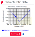
1206 - GRM31CZ71C226ME15, SRF 1MHz, 22uF

Sorry for being really confused here, based on the graph below, isn't operating at 1MHz, means the impedance is at it's minimal and that also means the capacitance is at it's minimum as well?
Thanks.

1618455604983.png


you often see small caps, 0603, then 0806, then 1206 from 10nF upwards paralleled to create capacitance that has a high SRF

operating a cap at it s SRF is not problem as long as the dissipation is low enough - the tracking to the cap will lower the res freq also ...
 

Attachments

  • 1618455417170.png
    1618455417170.png
    64.1 KB · Views: 232

Your filter caps have to suppress not only the switching
frequency but its harmonics, as far out as practical.
Above SRF the capacitor's ESL makes it less, rather
than more effective as frequency rises. Meanwhile
the filter inductor's interwinding capacitance is going
to let higher order harmonics "bypass" the inductor's
effort to hold down voltage ripple. You'd like that
"foot race" to be decided in your (EMI, output noise)
favor. You will have many more choices in capacitors
than in current- and frequency-suitable inductors.

Simulating the effect or various ESL and ESR nonidealities
on capacitor and an ideal or parasitics-degraded inductor
would be a good way to demonstrate this to yourself
and gain more of a "gut" understanding.
Yes, will simulate that using LTSpice. But would be good if there is some form of quick calculation to be able to judge if that group of capacitors with the respective SRF would be able to work on a certain regulator switching frequency.
Many thanks!
 

Hi,
Placing capacitor in parallel increases the overall capacitance, wouldn't that reduce the overall resonant frequency?
It will increase capacitance,
but it will also increase stray inductance, which is also responsible for resonance frequency.

So overall frequency will shift, but if you take external wiring into account, it's not clear whether up or down.

Klaus
--- Updated ---

Hi,

Connecting capacitirs in parallel:
* a big value capacitor in a big package (slow)
* a medium value capacitir in a medium size package
* a small value capacitor (usually with different - faster - ceramics) in a smaller package (fast).

The faster one has to be placed closer at the source of HF.
Important: Solid GND plane, multiple vias for each GND connection, short traces (is more important than wide traces).


Klaus
 
Last edited:
Does the capacitor configuration below helps? How do you calculate the resultant SRF
Just calc ESL for each cap , by looking at the SRF and capacitance.
Then use complex numbers, with the triplet of LC series circuits in parallel.
That gives you the overall impedance.

Self resonance freq is where its imaginary bit is equal to zero.
 

Just calc ESL for each cap , by looking at the SRF and capacitance.
Then use complex numbers, with the triplet of LC series circuits in parallel.
That gives you the overall impedance.
Only true under the assumption of ideal lumped components. Actually the wiring inductance of the parallel circuit is in the same order of magnitude as the ESL of individual capacitors. But even in the idealized case, the parallel circuit has more than one resonance.

Impedance curve plotted in the datasheet is achieved in a test fixture and gives an idea of the impedance that might be obtained in your circuit. The latest when you are considering parallel circuits of multiple capacitors we should look at an actual layout.

As already mentioned, capacitor SRF isn't the relevant figure when selecting an switcher output capacitor. There is no direct relation between SRF and useable switching frequency. You rather look at output impedance, filter attenuation, controller loop gain and phase margin.
 
Last edited:

    kakiitek

    Points: 2
    Helpful Answer Positive Rating
Status
Not open for further replies.

Similar threads

Part and Inventory Search

Welcome to EDABoard.com

Sponsor

Back
Top