Continue to Site

Welcome to EDAboard.com

Welcome to our site! EDAboard.com is an international Electronics Discussion Forum focused on EDA software, circuits, schematics, books, theory, papers, asic, pld, 8051, DSP, Network, RF, Analog Design, PCB, Service Manuals... and a whole lot more! To participate you need to register. Registration is free. Click here to register now.

[SOLVED] Selective Delay Off Timer

Status
Not open for further replies.

mcmsat13

Member level 5
Joined
Apr 24, 2013
Messages
94
Helped
4
Reputation
8
Reaction score
4
Trophy points
1,288
Activity points
2,287
Timer.jpg

Please I need help from the programmers in the house. I am not a programmer myself but if a code is generated, I can dump it into PIC or AVR and place the device into my circuit. This is all I can do in this MCU of a thing.
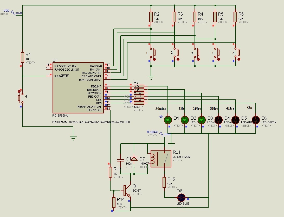
The diagram above is only pictorial representation of the Project. It does not necessarily means that the wires must run as they do here.
I have used CD4060 to do this but it makes things complex and the accuracy is somehow poor. Dam me! I am not a programmer!!
THE PROJECT:
To design a delay off timer
When the SW1 is closed, power is applied to the system but the system will remain inactive.
If the SW2 is pressed (push & Release button), the system will come on and the LED1 will be lit, consequently LED2 will also come on, showing that the system has entered 30 minutes delay off mode which if it remains in this mode, the relay RL1 will be activated if the 30 minutes elapsed.
The system will enter any timer mode from SW3 through SW7 if their respective button is pressed.
If the SW2 is pressed again while on, the system will go off and also reset itself.
Please I will appreciate any help from the programmers here, thanks all.
 

I can write a program for you. Can you use 8 pin PIC12F683 chip ?

- - - Updated - - -

Here is a PIC12F683 code. I have used mikroC PRO PIC compiler to write the code. I have compiled the code for Internal Oscillator 4 MHz. See image for circuit.
 

Attachments

  • Time Switch.rar
    65.7 KB · Views: 93
  • time switch.png
    time switch.png
    42.7 KB · Views: 117

Thanks my man, I am sorry for my late response. Please let me study what you sent me. I will get back to you.
Thanks.
 

circuit with AtMega 8 )
 

Attachments

  • atmega8 c hex proteus schm.zip
    51.6 KB · Views: 73
  • Like
Reactions: eril

    eril

    Points: 2
    Helpful Answer Positive Rating


@ pic-programmer,
This pic and code that you posted is not the PIC12f683 you talk of. Can I see the 8-Pin diagram and code for the PIC12f683? As far as it can do the work, it may be easier for me to handle. Remember, I am not deeply learned in MCUs as you.
I have simulated your design in Proteus isis and I am worried about some behaviors of the circuits. Unless the real life behaviors will be difference from the CAD simulation if not, then it will not do the work.
The pins, RB0, RB1, RB2 are = ‘1’ at power on consequently the LEDs D1, D2 and D3 are on.
Pressing Button 1, and 2 does not have any effect on the D1, D2 and D3.
Pressing button 3 will light on D4
Pressing button 4 will light on D5 and
Pressing button 5 will light on D6
Pressing button 6 will make all the LEDs off and back on as soon as you release the button
Is this right? I wonder if the hardware assembly will be the same.
How I want this:
At power on, RB0, RB1, RB2, RB4 and RB5 will be = ‘0’,
and if RA5 = ‘0’, then RB5 = ‘1’ and RB0 = ‘1’ and in 30mins countdown RB7 will be = ‘1’.
From now on as far as button 6 is not pressed again the D6 will remain on with any corresponding LED (from D1 to D5), depending on the timer chosen. The system will take command from any button pressed ( from Button 1 to 5)
Pressing any of the buttons 1 to 5 will make the one pressed last to take over the command and disable the one previously pressed just like mechanical button regulator of standing fan. The MCU will make port RB7 = ‘1’ according to the time selected.
Button 6 is just like the power on/off button. Anytime it is pressed, the system will return to off state and no LED will be on and when it is pressed again, RB0, RB1, RB2, RB4 and RB5 will be = ‘0’,
and if RA5 = ‘0’, then RB5 = ‘1’ and RB0 = ‘1’ and in 30mins countdown RB7 will be = ‘1’.

@ Deep One,
For Atmega8, I have also simulated it. It kept quiet at power on which is good. But pressing on/off button does not work, the pressing other buttons make their respective LEDs come all on without disabling the previous ones. Please see my post above.
 
Last edited:

Hi

I have fixed the code. there were two problems. Now it is working fine. Check the attached project. I have tested for 30 minutes and it works fine. In the proteus file I have added labels so that the schematic is easier to understand.
 

Attachments

  • Time Switch rev1.rar
    67 KB · Views: 92

Ok, please take a look on next revision
 

Attachments

  • atmega8 _c&hex rev1.rar
    7.5 KB · Views: 70

@ Pic Programmer and Deep One, I thank you. You are very useful here. I will check them out in Proteus.
Thanks.
 

In the rev1 code I have fixed two things. One is PORTB was not cleared during initialization and hence some LEDs were ON at startup. The second thing was in timer interrupt code instead of checking for 30 minutes, 60 minutes, etc... delays it was checking for 30, 60, 120, 180 seconds.
 

@ pic-programmer,
Thanks for the new edition ‘Time Switch rev1’
I have tested it and see the improvements. The problem in this new code is that if you select 30mins and then select another timer, the 30mins you previously selected will not deactivate. It remained on while the other selected timer will also be on. Pressing all the timers will bring all the timers all on. Then pressing the on/off button will reset all, this one is ok.
When any time is selected, selecting another timer should deactivate the one previously selected and so on.
Your relay action during power on is ok, only that I have left the time to elapse in Proteus but the relay did not activate after the expiration of 30mins!
@ Deep One,
Thanks for the new atmega8 _c&hex rev1 edition.
I have also tested your new code and it is 99% ok.
I have run the timer in Proteus and it works at the elapse timer (30mins tested, but I hope other will also work).
The only fault, but I hope it will be corrected, is that the relay comes on at power on.
Please, at power on the relay should not move at all. The PD7 Pin 13 of the ATMEGA8 should only be = ‘1’, at the elapse of the time selected.
At power on;
Relay = off. (PD7 Pin 13 = ‘0’)
After timer elapse;
Relay = on (PD7 Pin 13 = ‘1’)
This is the only thing that remains to be fixed in the code.

Thanks DEEP One and PIC-Programmer! I thank you very much for your times you spend to help me, I appreciate your good work.
 

next version )
 

Attachments

  • atmega8 _c&hex rev2.rar
    6.8 KB · Views: 66

DeepOne I thank you for your fast and dedicated responds.
I have tested your last file and it just work the same as the previous one.
As you can see, I have used the Q2 to force the Q1 go into off state until the end of timer elapse when the port PD7 Pin 13 will be "0", then Q1 will be on and then the relay will be activated. I can still use it like this if it cannot be corrected in the code. You have tried already.

See the attached file for the modification, if the fix can be done in the code then the Q2 will be removed.
 

Here is the rev2 of the PIC version. I had fixed two things. One is the timer was checking for 30, 60, etc,... seconds and LEDs not used had to be cleared when a button was pressed. Also I had to clear the minute and sec variables when a button was pressed. I have fixed all those things. I have also neatly drawn the Proteus schematic.

Sorry, I earlier mentioned it as PIC12F683. It can't be used. I meant PIC16F628A.
 

Attachments

  • Time Switch rev2.rar
    68.9 KB · Views: 72
Last edited:

atmega8 _Timer_ rev2.jpg

This is the picture of the modification
 

it just work the same as the previous one.
In my test that rev.2 version is work as - when power supply is on the Q1 is in off state, relay off, all LED off. First pressing the on/off button actuate 30 min countdown and also power led and 30min led, in this mode relay remain off and is possible switching between 30/60/120/еtc. time delays. If delay is expired relay is go to on state, time led is go off. If power button was pressed the system will return to initial state (relay off, all led off)
 

I have also made ATMega8 version of the project. Please have a look at it. I have tested it in Proteus and it works fine. I have used mikroC PRO AVR Compiler for writing the code but if you want it to be written in Atmel Studio or other compiler then mention it and if I have that compiler then I will make a code using that compiler.
 

Attachments

  • Time Switch ATMega8 4 MHz.rar
    68 KB · Views: 96
  • Delayed Turn On Switch.png
    Delayed Turn On Switch.png
    55.5 KB · Views: 86
You two are the best. I will check and see the best one that serves me.
 

In my test that rev.2 version is work as - when power supply is on the Q1 is in off state, relay off, all LED off. First pressing the on/off button actuate 30 min countdown and also power led and 30min led, in this mode relay remain off and is possible switching between 30/60/120/еtc. time delays. If delay is expired relay is go to on state, time led is go off. If power button was pressed the system will return to initial state (relay off, all led off)

Hello DeepOne,
I am a newbie, just learning the microcontroller, I am using mikroC AVR.

Look at your coding above, that the function is very smooth and great for me, so
Could you please convert your code to compiler MikroC PRO for AVR.

:grin::grin::grin::grin::grin:
 

Do you want the time delay LEDs to turn OFF when the delay expires and relay turns ON ?
 

Status
Not open for further replies.

Similar threads

Part and Inventory Search

Welcome to EDABoard.com

Sponsor

Back
Top