Continue to Site

Welcome to EDAboard.com

Welcome to our site! EDAboard.com is an international Electronics Discussion Forum focused on EDA software, circuits, schematics, books, theory, papers, asic, pld, 8051, DSP, Network, RF, Analog Design, PCB, Service Manuals... and a whole lot more! To participate you need to register. Registration is free. Click here to register now.

Selecting right resistor value for parallel diode operation

Status
Not open for further replies.

vindhyachal

Newbie level 4
Joined
Oct 16, 2015
Messages
6
Helped
0
Reputation
0
Reaction score
0
Trophy points
1
Activity points
100
1. I have a application in which I have to pass 10A current through diodes, diode here is for reverse current protection.
Since total current is 10A, I have connected 4 diodes in parallel PDS1040.

2. Cannot use mosfet here since I have already had PCB made. So have to go with parallel diodes.

3. I was reading on internet that if a series resistor in front of diode is connected & diode current can be shared equally between each other.

4. I want to know how to calculate this resistor value. What is formula used here.

5. Again please dont mentioned other sol like mosfet since I have already made PCB with 4 parallel diodes & 4 series resistor space in front of each of them.

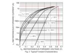
6. Attached is If vs Vf of PDS1040.
PDS1040-1.png
 

The resistors should have a sufficiently high value, so that the diode with least Vfwd does not hog current and burn up. It's possible that 1 or 2 ohms is sufficient.

This means you need to test many or all of the diodes, and get an idea how low an impedance they have. It can vary quite a bit, depending on individual V/I curves.
 

I see that each diode is capable of taking 10A individually. I presume you want each to carry 2.5A (approx; even with series resistors it will not be possible to say that each will carry exactly 2.5A). If you add 0.1 ohm in series, the resistor will drop 0.25V which is much more that the likely variation from manufacturing process. I suggest you use two 0.1R in parallel (one 0.1 ohm will dissipate 0.5W minimum) but if you have no space, just use a 1W 0.1 ohm resistor.
 

Hi,

if one diode is capable to carry the 10A, then I see no benefit in paralleling diodes.

Example:
According datasheet the voltage drop across the diode is about 430mV at 10A and 100°C. This means a total dissipated power of 4.3W.

Now use 4 diodes with optimal 2.5A each and a 0.1 Ohm Resistor each.
According datasheet there is a voltage drop at the diodes of about 300mV at 2.5A and 100°C.
Each resistor will add 250mV of voltage drop.
The total voltage drop will be 550mV.
Multiplied with the 10A this gives a power dissipation of 5.5W. This is 20% more than with the single diode solution.

The only benefit is that the dissipated power now is spread on 8 devices.
Probably it´s easier to install a heatsink on the single diode. --> less effort, less voltage drop, less power disspation.

Klaus
 

Status
Not open for further replies.

Similar threads

Part and Inventory Search

Welcome to EDABoard.com

Sponsor

Back
Top