Continue to Site

Welcome to EDAboard.com

Welcome to our site! EDAboard.com is an international Electronics Discussion Forum focused on EDA software, circuits, schematics, books, theory, papers, asic, pld, 8051, DSP, Network, RF, Analog Design, PCB, Service Manuals... and a whole lot more! To participate you need to register. Registration is free. Click here to register now.

Selecting and Changing Antenna on Testing Module

Status
Not open for further replies.

loserville929

Newbie level 4
Joined
Jun 15, 2015
Messages
7
Helped
0
Reputation
0
Reaction score
0
Trophy points
1
Activity points
64
4.jpg 5.jpg

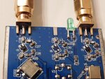
I'm working with a signal generator testing module and there are two antennas on it. One of them is for generating 400 MHz and another is 900 MHz (these are estimates).

Right now I'm stuck on how I can change the antenna/device so that I can produce different frequencies.

The 5th picture should show how the antennas look. I would like to make an antenna similar to that one.

Is there a way for me to change one of the antennas if I wanted to put a higher frequency?

or make a new antenna that can generate specific frequency?

Thanks
 
Last edited by a moderator:

View attachment 118495 View attachment 118496

I'm working with a signal generator testing module and there are two antennas on it. One of them is for generating 400 MHz and another is 900 MHz (these are estimates).

Right now I'm stuck on how I can change the antenna/device so that I can produce different frequencies.

The 5th picture should show how the antennas look. I would like to make an antenna similar to that one.

Is there a way for me to change one of the antennas if I wanted to put a higher frequency?

or make a new antenna that can generate specific frequency?

Thanks

What is the module to test? Do you want to test the generator, or the antenna? By what?

The frequency is determined by the generator, the antenna is used to send a signal away, to a remote receiver.
Depending on what is the receiver and how far from the transmitter it is located, you can use any antenna over a short range, or a directional antenna for a longer distance.

- - - Updated - - -

Your pictures do not show anything relevant. Do you have a schematic?
 

In every signal generator circuit carrier frequency will decide the operating frequency and which antenna is suitable for that application. So based up on your circuit frequency you can use corresponding antenna which will radiate at that frequency.
 

One of them is for generating 400 MHz and another is 900 MHz (these are estimates).

Typically that would be for 433MHz and 868/915MHz license free ISM bands.

Right now I'm stuck on how I can change the antenna/device so that I can produce different frequencies.

You would need to change antennas (easy) and the transmitters (difficult or impossible). If you only change the antenna, the module will use the same frequency as before, just with less range (antenna too short/too long for that frequency).

The integrated transmitter circuits have some limited bandwith over which they can be configured, but usually they are designed only for these ISM bands. The frequency is set by programming the transmitter chip, so you would need to (a) have a chip that can operate at your frequency of interest and (b) change the controller programming to use that frequency. And finally, change the antenna as needed.
 

Status
Not open for further replies.

Similar threads

Part and Inventory Search

Welcome to EDABoard.com

Sponsor

Back
Top