Continue to Site

Welcome to EDAboard.com

Welcome to our site! EDAboard.com is an international Electronics Discussion Forum focused on EDA software, circuits, schematics, books, theory, papers, asic, pld, 8051, DSP, Network, RF, Analog Design, PCB, Service Manuals... and a whole lot more! To participate you need to register. Registration is free. Click here to register now.

seeking help to modify 200 watt inverter.

Status
Not open for further replies.

liteon

Full Member level 2
Joined
Oct 13, 2010
Messages
149
Helped
27
Reputation
54
Reaction score
27
Trophy points
1,308
Location
PAKISTAN
Activity points
2,510
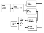
Please look at the attachment and suggest the better way to modify the schematics of the inverter for more power.The inverter schematics is for 12v to 220v 200 watt inverter with ferrite core transformer.
I need to modify it to go for 500 watts.
how can i do it? two more trafos. more mosfets at the output. What would be ideal way to connect more trafos and mosfets.
Where should i make the changes in the supporting circuitry to adjust it for 500 watts.
Please i need it urgent.
 

Attachments

  • 12v- 220v.GIF
    12v- 220v.GIF
    87.2 KB · Views: 124

Not really worth the trouble. The input DC-DC transformer size limits the maximum power capability. You might be able to raise the DC-DC converter freq slightly to get more power from the transformer. Then all the MOSFET's have to handle higher current.
 

actually i was thinking of putting another trafo in parallel to the existing one and drive it from the same outputs of sg3525 with another group of mosfets. Or using more powerful mosfets on primary side as well as on dc to ac inverter side.
I was thinking it may be possible so i asked to get conformation of its possibilities.i think the 4 irf740 can't handle 500w of power.125W is peak power for each irf740 so adding another group of 2 or more irf740 in series to existing mosfet will be enough with fairly large heatsink and cooling fan.
 

Sounds like it ought to work.

Do you plan to add another battery to power the second inverter?
Or use one 12V battery?

Because you're drawing 17 amps now.
However if you draw 34 amps....

you'll have 4x the power losses in the battery and in the cables (due to I-squared x R).

If you use a single battery your cables at the battery will need to be 6 awg or thicker to avoid overheating.
 

actually i already have two inverters. one is 12v to 220v 250 watt,other one is 12v to 220v 600 watts.From inside both have almost same guts but one with 250 watts has one EI core traffo and the one with 600 watts has two trafos in parallel and double the No of mosfets.The markings on the trafos of both inverters is same but i can see the second one has trafos wound with thicker wires.
The cables for the battery are already the thickest ones i can get,i did not measure but they look like as wide as human thumb and they are made from fine copper strands twisted together to make one fat wire.Perhaps they are automobile grade wires.
 

i did not reverse engineered the schematics for those inverters but i may do it if needed but i never did it before so it may take some time to do it.
So far i am trying to understand it and here it is as it looks in first sight.please look the attachment.
 

Attachments

  • inv.PNG
    inv.PNG
    9.3 KB · Views: 95

In theory the concept is fine. But only if you can ensure that both inverters are outputting equal voltage and/or current at all times.

In real life you'll probably have one inverter putting out higher voltage than the other.

Two things can result:

(1) One inverter will carry all or most of the burden. The other inverter will loaf until its output voltage exceeds the other.

(2) One inverter will send current back into the output stage of the other inverter, possibly destroying components.

It may be possible to add sensing circuitry which will let you equalize their output voltages. Or to equalize their output current.

Please ignore my post if you've already taken this into account.
 
  • Like
Reactions: liteon

    liteon

    Points: 2
    Helpful Answer Positive Rating
I am learning a lot from this discussion.Thank you very much BRADTHERAD.
Now i can figure it out this way that the circuit of inverter in my first post has a trafo without any feed back winding so the 200w original circuit will have no output voltage control.It will not adjust its output with increase in load.am i right?
Putting two inverters in parallel even if they share the same power source at input may not be balanced and definitely one will be taking the whole load specially with hand wound trafos.
I am going to ***** open one of the trafos of my 600w inverter and see the windings inside,
looking at the circuit board shows only primary and secondary windings. But after i De-soldered the trfo it looks like the input winding is not a simple one there must be some complex type of winding.
I will come back as soon as i ***** it open and figure out the winding details.
 

Now i can figure it out this way that the circuit of inverter in my first post has a trafo without any feed back winding so the 200w original circuit will have no output voltage control.It will not adjust its output with increase in load.am i right?

Right, you don't necessarily need regulated output in that case.

As to your plan to stack two inverters... I'm not saying it won't work. I'm only saying you'll be lucky if both inverters contribute their share right off the bat without some work.

Because now that I look back at earlier posts...

I see that your 600 W inverter consists of two inverters in parallel.

If this works then the method is shown to be feasible. It's a major accomplishment. (I know because I ran into problems building just one inverter.)

Is it your plan to add a third inverter to the twin inverters? This is worth a try.

Or do you plan to make a 500W version of the 600W inverter you have now?

In any case it's crucial to watch that no transformer overheats and no mosfet smokes.

Try to test the mosfets one at a time to make sure that they have matching ON-resistance. None must hog current. You can put your voltmeter across each mosfet to find out if any is acting like an oddball under power.

Same with the transformers. First test them individually under power with equal loads connected. You want to see equal voltage across equal loads. That's when it's safe to merge transformer outputs to one load.

How much difference is permissible between transformers? Or how many additional windings can one have and it still be okay? Not sure. You'll find out if one heats up more than the other.

It may be permissible to have a smaller (weaker?) transformer producing less current. However it should be at the same voltage as the other. How much difference can there be in output voltage? Not sure.

As you increase test load, you should keep putting your hands on all inverter components. Ideally every mosfet and transformer will just begin to get too hot to hold your hand on. Then you'll say "load limit reached."
 
Thank you once again BRADTHERAD.
I just opened one of the trafos from my existing 600w inverter.
it has 7 pins on primary and 2 pins at secondary.The primary pins are soldered in groups on the circuit board as 1-2-3 and 4-5 and 6-7.
The windings are a little fancy. 4*0.7 mm from pin 6-7, 3 turns ends at pin 1 . 1*0.7mm from pin 7 and 1*0.7mm from pin 6, wound as bi-filer, 3 turns and ends at pin 2.

2*0.7mm from pin 3 and 1*0.7mm from pin 2, wound as tri-filer 2 turns and ends at pin 4.

2*0.7mm from pin 3 and 1*0.7mm from pin2, wound as tri-filer 2 turns and ends at pin 5.

Since the pins are connected in groups at the circuit board as described above, so overall its connected as 2 secondaries with common pins group 1-2-3 connected to ground.
But the winding is made much complex which i don't know why.


Anyway i am not interested in adding a third inverter to my existing 600w inverter.I want to make one by myself as in first post but want it to deliver 500w at least. I already got two identical ferrite cores.But i may not be able to experiment it immediately because of work load at my business place. As soon as i will get the time i will try.
 

The wires at the primary taps are all the same gauge. This suggests they carry load (or could).

I think the large number of taps are there so the quality-control-man can hook up coils in different ways. He may want to achieve balanced action in the two halves of the transformer.

Or the extra windings are (or could be) used to sense when saturation is occurring.

Or which produce (or could be used to produce) pulses which sustain oscillations in the driver circuit.
 
  • Like
Reactions: liteon

    liteon

    Points: 2
    Helpful Answer Positive Rating
Just got some free time i wound two identical transformers according to the specification of the schematics in the first post.They will be left for a day or two to dry the lacquer and then ready after baking them .In the mean time i just ordered few components i,e diodes and resistors not locally available to me so have to wait for them to arrive.
Regards!
 

i thing the easy way do not changes any more for circuit simply make one more transformer i mean tow transformer use series and get it your requirement
 

Yes qayyoum brother you are right.
I idea came to my mind when i was not able to balance both transformers in parallel.
So i modified the transformers again to to put their secondaries in series.The circuit is now working since last three days for testing,so far looks good.
I am thankful to all members of the forum for their help.
Qayyoum brother from which city do you come. I am from BAHWALPUR.
 

Status
Not open for further replies.

Part and Inventory Search

Welcome to EDABoard.com

Sponsor

Back
Top