Continue to Site

Welcome to EDAboard.com

Welcome to our site! EDAboard.com is an international Electronics Discussion Forum focused on EDA software, circuits, schematics, books, theory, papers, asic, pld, 8051, DSP, Network, RF, Analog Design, PCB, Service Manuals... and a whole lot more! To participate you need to register. Registration is free. Click here to register now.

Schottky diode question

Status
Not open for further replies.

boylesg

Advanced Member level 4
Joined
Jul 15, 2012
Messages
1,023
Helped
5
Reputation
10
Reaction score
6
Trophy points
1,318
Location
Epping, Victoria, Australia
Activity points
11,697
I have a PC power supply that I am using as a bench top power supply for electonics. I noticed the -12V line is actually puting out about 11.17V.

I happened to find a forum post about boosting the voltage slightly and a suggestion to use a schottky diode to acheive this.

I actually tried it with a schottky diode that I salvaged from a tv circuit board and it seems to work quite well as long as I bias it correctly on the
-12V line. It takes the output voltage to about 11.88V

I am used to the idea that any load reduces the voltage rather than increase it and find it hard to get my head around how a schottky increases it.
 

I happened to find a forum post about boosting the voltage slightly and a suggestion to use a schottky diode to acheive this.
Sounds surprizing. Up to now, I thought that you either need an independent voltage source or an active switching circuit to "boost" a voltage. A schottky diode on it's own hardly can.
 

Sounds surprizing. Up to now, I thought that you either need an independent voltage source or an active switching circuit to "boost" a voltage. A schottky diode on it's own hardly can.

Well I dunno either. But it definitely seems to work. If I measure the voltage at the contact it is 11.17 - 11.22V.

If I measure at the diode the voltage seems to shoot up to about 13.6V and then slowly settles back to 11.8V
 

I actually tried it with a schottky diode that I salvaged from a tv circuit board and it seems to work quite well as long as I bias it correctly on the -12V line. It takes the output voltage to about 11.88V

I am used to the idea that any load reduces the voltage rather than increase it and find it hard to get my head around how a schottky increases it.

If this diode is used as a rectifier, resp. in series with the output voltage, the lower forward voltage drop of a Schottky diode (compared to a standard Si junction diode) is responsible for the larger output voltage.
 

If this diode is used as a rectifier, resp. in series with the output voltage, the lower forward voltage drop of a Schottky diode (compared to a standard Si junction diode) is responsible for the larger output voltage.

But can you elaborate on how it is acheiving this? I am afraidI just can't get my head around it? What has the lower forward voltage drop got to do with it?
 

If the diode is in series somewhere between the input and the output:

output-voltage = input-voltage - (Vf = forward voltage drop of the series diode)

... the lower voltage drop of a Schottky diode allows for a higher output-voltage.

Silicon junction diode: Vf ≈ 0.7V
Silicon Schottky diode: Vf ≈ 0.4V


img87.gif


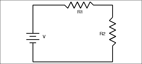
Let's assume the schottky acts like on of the resistors in this circuit where its voltage drop is given by 0.4V = IR. And Vcc = 11.17V.

My HSC physics is telling me the voltage on the other side of the diode should be 11.17 - 0.4 = 10.77V

I still don't 'get' your explanation I am afraid.

How does 0.4V dropping across a 'resistor' result in the voltage measured between the other end of the diode and ground being 11.8V?
 

The Schottky Diode has lower voltage drop, resulting on higher voltage output if the diode is in series.
 

If I measure at the diode the voltage seems to shoot up to about 13.6V and then slowly settles back to 11.8V
You didn' tell about the measurement condition. The descriptions sounds like you have connected a large capacitor but about no load current. In this case, the capacitor will store possible overshoot during switch on and also charge up to the peak value if a ripple voltage exists.

If you apply reasonable load current, you'll hardly observe a voltage increment. Or you invented a new kind of perpetual motion :smile:

Perhaps the fact that it is schottky diode has nothing to do with what I am observing.

Perhaps inserting any load between the DMM probes and the power supply pins has some other effect on the power supply circuitry that increases the voltage output slightly.

But what of this fellow stating that a schottky increases the voltage slightly? Perhaps I have misunderstood the context.
 

I came across a website that was discussing negative resistance as it relates to schottky diodes and that this can be a mechanism for them acting as a voltage amplifier in a voltage divider situation. I didn't save the website so I can't post it here. Haven't quite got my head around it and I have been trying to find the website again.

The way I was measuring the voltage with my DMM was effectively a voltage divider situation with the DMM forming the the other large value resistor.

Perhaps this explains why I was reading a slightly increased voltage from the power source.
 

You're thinking of tunnel diodes not Schottky diodes.
 

Hint: Don't try using Tunnel diodes as your rectifiers ! :lol:

Those of us who have worked with Tunnel diodes or tried to buy them will understand the problem !!!

Brian.
 

From what I am aware of, I think that Tunnel Diodes are the only ones who have negative resistance in some part of their characteristic. There is also Gunn Diode, that has that kind of characteristic. It is used for high-frequency.

Best regards.
 

gunn diode in lower frequencies is a poor negative resistant device
but in higher frequencies it has no equals

where as the tunnel diodes have wide band width over which they can serve as a rectifier
 

I am sure that I read that Schottky diodes can also have negative resistance under some circumstances.

Try to find that reference in your browser history, I am curious to see it.
 

I fear, the discussion is double confused. Even if we could impute schottky diodes with a negative differential impedance similar to tunnel diodes, it's nowhere near to an absolute negative impedance as required to boost a voltage.
 

Try to find that reference in your browser history, I am curious to see it.

Did I specifically say that it was -11.17V to -11.8V? Or did I omitt the -?

I didn't try it on the +12V line as this was close enough to +12V.

It might make a difference to this discussion.

Looked through my history but have not found it yet.


UPDATE.....

After continued searching I cannot find any reference to negative resistance with schottky diodes or with using them to increase supply voltage.

But I would still like some sort of explanation for my measurements of negative output voltage when I make the measurment through a schottky diode.

Perhaps I should try again with a rectifier diode and a resistor.

So I can only conclude that I have misunderstood what I have read with the negative resistance thing and either similarly misunderstood precisely what was being discussed with the supply voltage thing or the credibility of of the poster was questionable.

- - - Updated - - -

This is interesting......might go some way to explaining my voltage readings with and without the schottky diode.

http://forums.anandtech.com/showthread.php?t=1213382

12-14-2003, 07:09 PM #7
Jhhnn
Lifer


Join Date: Nov 1999
Location: Denver Co
Posts: 16,049 RE: My -12V voltage rail on my power supply reads -13.01V?

--------------------------------------------------------------------------------

Don't worry about the -5v, either, it also does nothing. The newest atx specs at www.formfactor.org allow for elimination of the -5v, the -12v will be the next to go...

The reason that they'll often read strangely is that the psu has a very difficult time regulating a near zero current draw...


Jhhnn
View Public Profile
Find More Posts by Jhhnn

12-14-2003, 07:32 PM #8
Soulkeeper
Diamond Member


Join Date: Nov 2001
Posts: 5,300 RE:My -12V voltage rail on my power supply reads -13.01V?

--------------------------------------------------------------------------------

the negative voltage readings are hardly ever in spec
probably because they have no or little load on them

__________________
 
Last edited:

Status
Not open for further replies.

Similar threads

Part and Inventory Search

Welcome to EDABoard.com

Sponsor

Back
Top