Continue to Site

Welcome to EDAboard.com

Welcome to our site! EDAboard.com is an international Electronics Discussion Forum focused on EDA software, circuits, schematics, books, theory, papers, asic, pld, 8051, DSP, Network, RF, Analog Design, PCB, Service Manuals... and a whole lot more! To participate you need to register. Registration is free. Click here to register now.

Schmitt trigger with low power consumtion at all input voltage range from 0 to VCC

Status
Not open for further replies.

Kirr

Newbie level 4
Joined
Mar 17, 2015
Messages
6
Helped
0
Reputation
0
Reaction score
0
Trophy points
1
Activity points
43
Greetings.
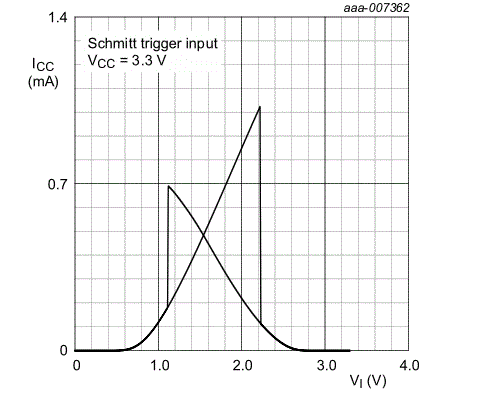
I have a task to design an input circuit for IC I/O pad which should have typical threshold voltages for Schmitt triggers at 3.3V technologies, e.g. Vth+ = 1.6V and Vth- = 1.2V. Moreover it should have <10uW DC power consumtion for all possible input DC voltages. Thats why traditional Schmitt trigger is unsuitable for this application, because it has a significant current consumption at the middle of Vin range (see the pic).
9447249900_1477766738.gif


I'm wondering is it possible to design circuit for my case without using analog comparators which allows to define hysteresis loop very simple but has a disadvantage of permanent current consumtion however which is independent of the input voltage?

If you have any useful papers or experience for this kind of circuits please share it. Thanks in advance!
 

That increase in current helps the output state to change, so lowering it is going to inherently reduce your bandwidth somewhat. So you need to specify a speed requirements at least. A low power comparator IC will likely be your best bet.
 

There will -always- be a crossover current at the back
end where you're flipping CMOS inverters.

In my experience the best way has been to make a
micropower comparator (can be crude) followed by
a couple of minimum inverters (maybe resistor limited)
to sharpen up the edge, then followed by your taper
chain to get whatever drive you like. You can easily
get your hysteresis (and better controlled) using the
comparator with some feedback (think MOS resistors
or a switched series Vgs, depending on how much
hysteresis you want).

Because hysteresis pops the inverter chain north or
south at any given voltage, you can get to only the
bias current of the comparator.

You say you don't want analog comparators, but you
can get one to run on a microamp which fits within
your asserted Idd budget. So what's the beef?

You can look at the Yoo buffer, but it's only slightly
different than the CMOS Schmitt (hard to see the
difference, when I looked). Using resistors in the drain
or source legs of front end inverters can tamp down
the crossover current and get you a better, but
probably still short of the goal, peak current. I am
not the only guy who's ended up with a comparator
front end, chasing the same things you are.
 

Hello friends, thanks for your answers, i hoped there maybe more elegant circuit exists, but i assume that analog micropower comparator will be the simplest and suitable solution
 

The bottom line is that an increase in Idd is unavoidable as the thresholds are approached, since the transistors will be biased towards saturation instead of cutoff/triode. That's just how amplifiers work. In a comparator circuit, it's easy to know what that peak Idd is from the diff pair, since it can't go higher than the set bias current.
 

Hi,

with a comparator the input stage is supplied by an internal current source.
Therefore I assume the supply current consumption is rather constant. But usually higher than a schmitt trigger logic gate (with input levels close to the supply rails).

Klaus
 

Status
Not open for further replies.

Similar threads

Part and Inventory Search

Welcome to EDABoard.com

Sponsor

Back
Top