Continue to Site

Welcome to EDAboard.com

Welcome to our site! EDAboard.com is an international Electronics Discussion Forum focused on EDA software, circuits, schematics, books, theory, papers, asic, pld, 8051, DSP, Network, RF, Analog Design, PCB, Service Manuals... and a whole lot more! To participate you need to register. Registration is free. Click here to register now.

sample and hold circuit

Status
Not open for further replies.

akbarza

Full Member level 2
Joined
Dec 18, 2013
Messages
131
Helped
0
Reputation
0
Reaction score
0
Trophy points
1,296
Activity points
2,556
hi
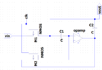
can any one explain to me how the attached circuit works? especially in holding phase?
the pic belongs to below paper :
"A high-speed sample-and-hold technique using a Miller hold capacitance"
P.J. Lim ; B.A. Wooley- https://ieeexplore.ieee.org/document/75067

thanks sample&hold.PNG
 

It doesn't work- you've got a floating input. Where does the noninverting input go?
 

N.I. input grounded.

As described in the paper, it's a modified open loop SH topology. In hold phase, you have holding capacitor C2 multiplied with OP gain A. The main purpose of the circuit is however in managing switch charge injection during transition phase.
 

Status
Not open for further replies.

Similar threads

Part and Inventory Search

Welcome to EDABoard.com

Sponsor

Back
Top