paradiseseeker8
Newbie
How to create an S-parameters model for a surface mount resistor in microwave? let's say for 0805 or 0603 with value 120 ohms and frequency range 2GHz to 12GHz.
Thanks.
Thanks.
Follow along with the video below to see how to install our site as a web app on your home screen.
Note: This feature may not be available in some browsers.
but the number of s-parameter files provided are very few and they are modeled for the regular resistor values such as 50 ohms, 100 ohms and 1 kohms but specific value such as 120 not available.
Modelithics CLR library as I noticed it is for the regular values .
I'm still newby this topic, so excuse me how to EM simulate it?
How to create an S-parameters model for a surface mount resistor in microwave? let's say for 0805 or 0603 with value 120 ohms and frequency range 2GHz to 12GHz.
Thanks.

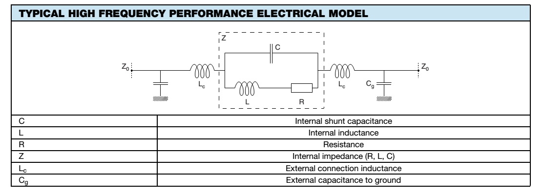
The problem with your model is that all shunt capacitance is missing, so this is not accurate enough. The model topology in the Vishay data sheet is more accurate ... but unfortunately they have not provided any values.

The problem with your model is that all shunt capacitance is missing, so this is not accurate enough. The model topology in the Vishay data sheet is more accurate ... but unfortunately they have not provided any values.
")
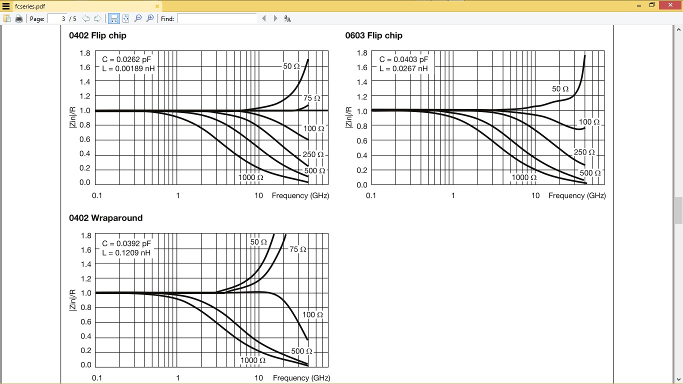
With the series I suggest LC values are given for each case size. (smaller is better)
R values are shown in graphs. This does not include external parasitic elements.
Hmm…….but……..my model……is just based on Vishay.
all shunt capacitance is missing ?
With the series I suggest LC values are given for each case size.