Continue to Site

Welcome to EDAboard.com

Welcome to our site! EDAboard.com is an international Electronics Discussion Forum focused on EDA software, circuits, schematics, books, theory, papers, asic, pld, 8051, DSP, Network, RF, Analog Design, PCB, Service Manuals... and a whole lot more! To participate you need to register. Registration is free. Click here to register now.

Running opamp off voltage divider, a good idea or not?

Status
Not open for further replies.
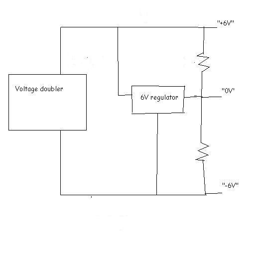
There was a ground node in my circuit - I guess you missed it. Make your R3=0.

Keith
 

By the way, I cannot be certain but normally I would expect the largest capacitor across the piezo and the one in series with the inductor to be a lot smaller. That results in very large inductance values, but that is normal for a crystal model I think.

Keith.
 

I've had another go and put the ground in properly. The circuit does work I think, in that I get the LC peak. I'm looking to get an anti resonance trough. I'm struggling to remember exactly what the frequency distribution should look like.

Regards,

Ant.
 

You will need to increase the series resistor to see the two resonances. The low value is useful for finding out the series resistance. Also, as I mentioned earlier, I think the large capacitor should be parallel.

Keith.
 

I've found what the frequency spectrum should look like. The picture is a bit grainy.
I'll know I have simulated it properly when it looks like that.

I'm working with this circuit now. Regards.
 

You did it. That was cool. I'm laughing because I'd posted without seeing you'd done it :) I'll try your circuit now.

Added after 19 minutes:

The output curve I have does look like my grainy picture. I will change values and see what it affects, I still have attenuation for example. Thanks!
 

If you are working with piezos you ought to download Morgan Electroceramics' book:

**broken link removed**

When trying to match your circuit to the model, use a small series resistor to try to get the dip and tweak the series resistance in the model. Then use a larger resistor to get the height of the peak - in each case setting up the same test circuit on the bench with a signal generator (or spectrum analyser with tracking generator if you have one). The spectrum analyser probably limits you to only 50 ohms, but can still be useful. Here is a real one.

Keith.
 

    ants

    Points: 2
    Helpful Answer Positive Rating
May I suggest an alternative approach to the virtual earth? Although the thread has rather moved on!
What about using a 3-pin power supply regulator, driving and correcting a potential divider which is set somewhat below Vs/2.
I imagine this may provide a suitable hard reference.


    ants

    Points: 2
    Helpful Answer Positive Rating
Hi Keith,

I have a signal generator but not a spectrum analyser, I'd like one of those but I think when I looked them up they were thousands of pounds. The morgan book looks helpful and on topic I will have a read.

The methodology has me in a bit of a tizz because I have a real life piezo which I need to make up as a similar electric circuit and then model in LTspice.

Hi Poor mystic,

I hadn't thought of that but it would work. I also have some spare regulators, I bought 6 of them so will have some left over. That is a good idea. Thanks.
 

ants said:
Hi Keith,

Hi Poor mystic,

I hadn't thought of that but it would work. I also have some spare regulators, I bought 6 of them so will have some left over. That is a good idea. Thanks.

Be careful with that approach. It may be OK but regulators generally only source current, not sink it. If something tries to pull up the mid rail point the regulator won't be able to stop it.

Keith
 

keith1200rs said:
ants said:
Hi Keith,

Hi Poor mystic,

I hadn't thought of that but it would work. I also have some spare regulators, I bought 6 of them so will have some left over. That is a good idea. Thanks.

Be careful with that approach. It may be OK but regulators generally only source current, not sink it. If something tries to pull up the mid rail point the regulator won't be able to stop it.

Keith

Thanks Keith. Of course there must be some power wasted in the exercise; the regulator must fight the potential divider, which is set to a convenient voltage and source resistance..
 

I have used the MAX1886 & LM8261 in the past to generate high performance virtual earths. There may be better devices around now. Also, TI used to make a 3 pin virtual earth device TLE2425/2426.

Keith.
 

I'll keep the splitter thought in mind.

I had a look at the TLE2425/6 a while back. They still make them but they are upto around 300mA whereas I need 1A or more.

Regards,

Ant.
 

ants said:
I'll keep the splitter thought in mind.

I had a look at the TLE2425/6 a while back. They still make them but they are upto around 300mA whereas I need 1A or more.

I am suggesting them as a virtual earth for the opamp, not to power the whole circuit!

Keith.
 

Lol. I thought they did power the whole circuit.

Added after 5 minutes:

I mean with my set up i'll be looking to get 1A from the voltage divider to go into the opa548 as a dual supply. I will accommodate any change in the voltages. I'm not exactly sure how the TLE2425 works, I used as my reference as to what to do the page here. It gives an outline to the options for creating a dual supply from a single one.

https://tangentsoft.net/elec/vgrounds.html
 

ants said:
Lol. I thought they did power the whole circuit.

Added after 5 minutes:

I mean with my set up i'll be looking to get 1A from the voltage divider to go into the opa548 as a dual supply. I will accommodate any change in the voltages. I'm not exactly sure how the TLE2425 works, I used as my reference as to what to do the page here. It gives an outline to the options for creating a dual supply from a single one.

https://tangentsoft.net/elec/vgrounds.html

I'm confused. Your original problem was to create a virtual ground from a couple of resistors for the OPA548. The TI devices should easily do that. The supply current for the OP548 should still be coming from the switching regulator in your circuit.

:?

Keith.
 

I'm wondering how I could use the TLE2425 now. I could change my earlier remark to "Lol. I wish I knew how to do that." But I think I should stick to the voltage divider and only consider more complication if it doesn't work.

Thanks for your input Keith and poor mystic.

Added after 13 minutes:

keith1200rs said:
I'm confused. Your original problem was to create a virtual ground from a couple of resistors for the OPA548. The TI devices should easily do that. The supply current for the OP548 should still be coming from the switching regulator in your circuit.

:?

Keith.

I didn't know that. I was laughing at my own lack of knowledge not yours, it was poor wording. I have enjoyed the conversation and it has been very helpful.

Regards,

Ant.
 

Status
Not open for further replies.

Similar threads

Part and Inventory Search

Welcome to EDABoard.com

Sponsor

Back
Top