Continue to Site

Welcome to EDAboard.com

Welcome to our site! EDAboard.com is an international Electronics Discussion Forum focused on EDA software, circuits, schematics, books, theory, papers, asic, pld, 8051, DSP, Network, RF, Analog Design, PCB, Service Manuals... and a whole lot more! To participate you need to register. Registration is free. Click here to register now.

RUBY AMP CIRCUIT (not turning on)

Status
Not open for further replies.

bzblues

Full Member level 1
Joined
Oct 11, 2020
Messages
99
Helped
0
Reputation
0
Reaction score
2
Trophy points
8
Activity points
822
Hello!

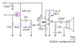
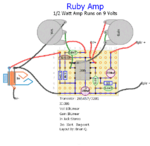
I'm building my first Ruby guitar amp with the LM 386. I know its a very simple circuit, but I can't get it to work.

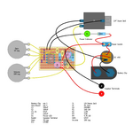
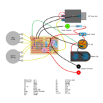
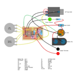
Since I don't know how to read schemantics propperly (I'm learning!) I found a wiring diagram very easy to follow.

I put everything together, I checked, double-checked, TRIPLECHECKED every component, and everything is where its should, but it does not turn on.

I checked continuitty with the tester and in some places it has and others don't, since its the first time for me doing this, maybe I'm makeing a mistake. Also checked that the Voltage is getting to the board and it does, but still doesn't work.

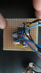
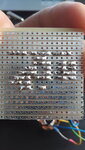
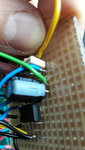
Also I made sure to do the cutting points of the veroboard real neat, like in the picture, but perhaps there is the mistake.

I'll post a few pics.

Thank you in advance for your help!
 

Attachments

  • RUBY AMP.png
    RUBY AMP.png
    188.5 KB · Views: 676
  • 20201014_141155.jpg
    20201014_141155.jpg
    1.2 MB · Views: 343
  • 20201014_141106.jpg
    20201014_141106.jpg
    1 MB · Views: 328

Aww! you made it hard to trace by rotating the board between pictures!

First, I feel I must point out that you are using a low power, high distortion and high noise amplifier that is far inferior to modern devices, it should still work though.

Is anything happening at all? You should hear the hiss of the amplifier even with no input and the volume turned down.
Please place the negative probe of your voltmeter on the negative side of the battery then check the following and let us know what you find:
1. The voltage on each pin of the IC.
2. The voltage on the drain pin of Q1. (with the flat side facing you and the pins pointing downward its the pin on the left)

I should point out that at first glance, the 'schematic' first picture looks wrong to me.

Brian.
 

Hi! I check the voltage on the IC and the Q1 and the is a flow, but not even the LED is turning on, its like completely dead! but voltage is flowing, so I'm kind of lost. Maybe as you say, there is something wron in the drawing wiring. Here are the schemantics for you to compare. I still don't know how to read it :S

Thank you!
 

Attachments

  • ruby.png
    ruby.png
    2.1 KB · Views: 225

I suspect the problem is nothing more than no power is actually reaching the board. The layout drawing shows there is a switch inside the jack socket that turns the power on when a plug is inserted. If you are using a different type to the author the switch may not be present or it could be on different pins. Try this:

Take the negative (black on the diagram) wire from the battery and solder it to the top horizontal strip on the board - the same strip that C3 and D1 are already soldered to.

If that doesn't work, TEMPORARILY move the positive (red on the diagram) and connect it to the pin marked '+' on the DC 9V socket so the battery is effectively wired straight through to the switch. If you have a power adapter, do not plug it in to the 'DC 9V' at the same time as a battery is clipped in while it is wired this way.

Let me know what happens.

Brian.
 

Yes, indeed I´m using a common 1/4 inch stereo jack, with 2 positives and 1 negative. It looks like the jack used in the drawing is the one you say, but if it is that one, it would make no sence to have a on/off switch, because that would be the job of the this kind of jack, am I right? or its they can be both there?

Before trying, I'll attach a drawing to see if I understanded correctly what you told me. If its like the drawing, the problem is that the negative lug of the jack is not connected, only the two positives.
 

Attachments

  • RUBY AMP new.png
    RUBY AMP new.png
    266.9 KB · Views: 340

That's exactly what I meant. The new green wire become the negative power connection to the board.

I'll explain my reasoning: Jacks do not have positive or negative 'sides' but they do have a common connection and one (mono) or two (stereo) signal connections. On SOME sockets there is also a switch, it is built in to the body and operates when a plug is inserted. On a mono socket like the one in the article the switch is used to disconnect the loudspeaker so that signal is diverted into the jack plug instead. You will have seen this when inserting a headphone/earphone plug also opens the switch to stop sound coming out of the loudspeaker on audio equipment. In this amplifier, the designer has used the switch to disconnect one side of the power to the board. If you have not used the same kind of socket the switch may not actually be there so it never turns the power on when a plug is pushed in to it.

Rewiring as it is in your new diagram bypasses the internal switch in the socket so the power is always connected, you can still use the manual switch to turn it off if you want to.

Brian.
 

Sadly it didin't work. I sodler the green wire lile in the picture, but still nothing. I've tryed with a 9V battery and also with a DC adaptor of 9V 1AMP, but nothing.

About the TEMPORARY wiring, should I return the wire that I moved to the board to its original position on the DC adaptor or should it stay there? I tryed before to eliminate the DC adaptor just to power the circuit with the 9V battery, but nothing happened. As you said, maybe there is something wrong in the picture. I checked many times and I placed every component where it should be, so my only guees is that the picture is wrong or something!
 

Until it is working I would leave the wire in the new position. Basically, the 'DC 9V' also has a switch in it that disconnects the battery when you plug the adapter in. As long as you use the adapter OR the battery there is no problem but you shouldn't connect them both at the same time while the switch is bypassed as it could damage the battery.

I think you need to go back to post #2 and report the voltages you find. Keep the negative side of the testmeter on the negative side of the battery and set the meter to read voltages. Move the positive probe to each pin of the IC in turn and let me know what voltage the meter shows.

Brian.
 

Hi Brian! I did the readings with only the DC adaptor plug in to the wall. So, I'll attach the picture with the voltage readings on the IC. Let me know if its normal

Thank you!
--- Updated ---

I think I should try to do this configuration. To reduce the humming I should use shielded wire to make the connections between the components, right? or just shielded wire from the battery to the PCB?
 

Attachments

  • RUBY AMP new.png
    RUBY AMP new.png
    271 KB · Views: 720
  • RUBY 2.png
    RUBY 2.png
    91.7 KB · Views: 219
Last edited:

Pins 3 and 4 of the LM386 are both connected to 0V (the negative side of the battery) so you shouldn't measure 1.31V on pin 4. It means you have no connection to pin 4 for some reason. Are you sure the 1.31V isn't on pin 1 rather than pin 4?

The Ruby 2 diagram has a serious error, the input jack connections are reversed. You only need screened cable for the signal input to the jack and between the jack and the circuit board but the screen is the outer braided layer of the cable and it should be connected to the 0V side. On a jack plug the 'body' cylinder of the pin is ground and the tip carries the signal, on the socket, the pin joined to the ring around the hole is ground and the furthest contact is the signal. When the plug is inserted, the screen on the plug connects to the ground side of the socket and the signal wire connects to the signal wire. When it is reversed you will pick up interference from the cable, you would have the screen signal being amplified instead of the signal you are trying to protect.

Brian.
 
Sorry!!! made a mistake in the picture! the 1.31 is in pin nº1 ! the rest of the pins in the left row show 0V
 

Attachments

  • RUBY AMP new.png
    RUBY AMP new.png
    273.1 KB · Views: 461

Pins 3 and 4 of the LM386 are both connected to 0V (the negative side of the battery) so you shouldn't measure 1.31V on pin 4. It means you have no connection to pin 4 for some reason. Are you sure the 1.31V isn't on pin 1 rather than pin 4?

The Ruby 2 diagram has a serious error, the input jack connections are reversed. You only need screened cable for the signal input to the jack and between the jack and the circuit board but the screen is the outer braided layer of the cable and it should be connected to the 0V side. On a jack plug the 'body' cylinder of the pin is ground and the tip carries the signal, on the socket, the pin joined to the ring around the hole is ground and the furthest contact is the signal. When the plug is inserted, the screen on the plug connects to the ground side of the socket and the signal wire connects to the signal wire. When it is reversed you will pick up interference from the cable, you would have the screen signal being amplified instead of the signal you are trying to protect.

Brian.


Hi Brian! I've manage to fuond the exact plug that it is used in the circuit aaaand...didn't work out. So, I don't know what else todo. I'll try another type of amp and keep on practicing . Thank you for the advices! all the best, my friend.

Brian Z.
 

The voltages look fine - what loudspeaker are you using and when you switch on, do you hear a 'pop' in the loudspeaker?

Brian.
 

I'm using a 4W 8 ohm speaker, but with the speaker connected or not, with or without the guitar cable plugged, the amp wont turn no. There is no pop, no light, no nothing. So, I'm out of ideas here haha.
 

I'm beginning to suspect you have two different problems.
By measuring the voltages you have established the amplifier seems to be powered up and the voltages are what I would expect so it is probably working fine. That raises two things:

1. The LED should light up regardless of whether the amp is working or not, it is simply wired across the battery with a series resistor to limit its current. If it isn't lit up the most likely reason is the LED is reversed. It could also be that the resistor R4 is MUCH higher in value than it should be but that is unlikely.
Switch it on, then measure the voltage across the LED with your meter. Put one probe on one side of the LED and the other probe on the opposite side. Assuming you are using a normal indicator LED, you should measure between 1.5V and 2V. If it is higher, you probably have the LED reversed.

2. Pin 5 of the LM386 is the amplified output to the loudspeaker, it has about 4.5V on it which is correct, it should be half the battery voltage. If 4.5V is connected to the loudspeaker through the 220uF capacitor C4, a spike of current will flow as the capacitor charges up and it should make an audible 'pop' from the loudspeaker. It's difficult to see on the photographs but can you check you have the loudspeaker wire soldered to C4 and not to the other side of the cut in the track nearby.

Brian.
 
The LED reads 1.52V so it should work. The possitive terminal of the speaker is in the right place just like in the drawing. Is the green wire in the picture
 

Attachments

  • 20201019_160818.jpg
    20201019_160818.jpg
    1.1 MB · Views: 171

This is mystifying! I can't see anything wrong and an LED with that voltage across it should be lit up.
I'm sure there must be a common error that stops the LED and amplifier working but I can't see it in the pictures. Can you show me a picture of the wiring so I can see the battery and LED and how they are wired together please.

Brian.
 

If R4 really is 4.7K (yellow,violet,red) the LED won't be as bright as it could be but it should still light up enough to be clearly seen.
Everything is battery powered so keeping the LED current as low as practicable is a good thing - it maximizes battery life.

Brian.
 

The LED is connected backwards and the value of R4 to limit its current is wrong.

So, this could be the root of the problem and simply not make it turn on? I'll try it then! I didn't realize that! I'll let you know if that solves the problem. Thank you.
 

Status
Not open for further replies.

Part and Inventory Search

Welcome to EDABoard.com

Sponsor

Back
Top