Continue to Site

Welcome to EDAboard.com

Welcome to our site! EDAboard.com is an international Electronics Discussion Forum focused on EDA software, circuits, schematics, books, theory, papers, asic, pld, 8051, DSP, Network, RF, Analog Design, PCB, Service Manuals... and a whole lot more! To participate you need to register. Registration is free. Click here to register now.

RS485 communication ground issue

Status
Not open for further replies.

ajit_nayak87

Member level 5
Joined
Oct 30, 2017
Messages
86
Helped
1
Reputation
2
Reaction score
1
Trophy points
8
Activity points
981
Dear all,

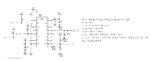
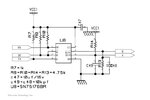
I have product which uses isolated and non isolated RS485 communication. I have issue with isolated design. I have used ADM2483 rs485 transceiver for communication. I have setup like this. by seeing this its obvious that unless i have 85-270vac aux supply i will have communication. since ground are different
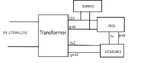
i dont have issue with above setup. problem occurred when i introduce battery charging unit here. same 12v and ground are connected to 12V/gnd . i found communication has stopped . if i remove battery charging unit it started working again.

i have tried making communication ground of converter to secondary ground of adm2483 , but it didnt worked
i have tried using 100E termination resistor but it didnt worked.

my question over here is
1) if i wanted to make in all prospects means if i removed 85-270v ac primary connection also with 12V standby how can i make it work. usually how isolated design will work

2) weather for isolated design primary and secondary ground which are galvanized isolated can be made common??

3)Is there any article where above case i can implement??.

4) is there any alternate transceiver in non-isolated design which pin config is similar to adm2483
 

Attachments

  • Isolated+design.JPG
    Isolated+design.JPG
    69.9 KB · Views: 136
  • Non-isolated+design.JPG
    Non-isolated+design.JPG
    41.5 KB · Views: 156
  • setup.jpg
    setup.jpg
    27.8 KB · Views: 129

Hi,

Your pictures miss to show the GND wiring inside the boxes.
And they miss the RS485 wiring.

Klaus
 

I have external connection as shown in Fig. Yes I have made ground common even its not shown in the figure.

All ground of Devices and RS485 converter is made common but fails to work when ADM2483 (isolated design ) product used.

I have question weather GND isolation can be made common. means ADM2483 uses isolated ground and isolated 5V supply . IN design internally used from transformer itself.
 

Attachments

  • CONNECTION.jpg
    819.9 KB · Views: 99

HI,

from your picture I can´t see which RS485 signal refers to which GND and where the isolation takes place.

Klaus
 

A RS-485 "connection" needs 2 data signals and a ground. Some voltage drop/difference is allowed for the ground connections, but it is a bad practice to have the 2 data signals as the only galvanic connection. Your isolated design should have one ground connection on each side of the isolation. All interfaces with the data lines connected should also have the related ground connections wired together.
 

RS-485 does not need ground at all.
It is balanced differential line.
All you need are A and B terminals on master/slave.
RS-485 is differential but not galvanically isolated like twisted pair ethernet.
The common mode range for RS-485 is only -7V to +12V. You don't want the signal wires to be responsible for keeping the common mode voltage within this range. Coupled "disturbances" will create unwanted common mode currents in the signal wires if there is no galvanic ground connection between the devices.

Twisted pair ethernet interfaces always have transformers for the signal wires and are specified for 1500V common mode voltage.
There is normally no need for a common ground.

RS-485 connections with the signal wires being the only galvanic path often work, but is a very bad practice.
The standard says that there should be a common ground, but it may not be neccessary with a dedicated wire. As an example, the protective earth (PE) can act as the common ground.
The RS-485 standard is not free, but are referenced in Wikipedia:
"the TIA standard requires the presence of a common return path between all circuit grounds along the balanced line for proper operation".

TI has this free document:
From section 4.5:
"Commonly RS-422 and RS-485 system configurations are presented without a separate ground wire. Laws of physics, however, still require a solid ground connection to ensure error-free communication between drivers and receivers."
 

If I understand the problem description correctly, it reports failure of isolated RS-485 interface. If not using a ground connection along with the differential pair, an isolated interface should use a low impedance bias network (a few 100 ohms pull-up and pull-down resistors) that keeps the common mode voltage within the permitted range. Without it, common mode currents injected e.g. by the power supply will possibly overload the RS-485 receiver. PROFIBUS is an example of a RS-485 based network using isolated transceivers without a common ground but mandatory bias resistors.
 
Last edited:

Its micro-controller based design
1)My question over here. When my test setup is added with Battery charging unit why it fails to communicate. (internal connection shown in thread1) .external wiring shown in thread3).
My product is working with aux 85-270VAC/DC connected & 12V battery backup. I havent changed setup but only introduce battery charging unit here.

2)By seeing my first circuit thread 1 . it understood that my communication will work only when aux 85-270VAC/DC supplied. since transformer output generate 12V 1A & 5V,500mA output. when there is no aux supply only 12vDC is powered from battery supply ,5V,500mA will not be generated which i have used to power Secondary of ADM2483. In this case my communication fails.

3) I would like to know what design should be implemented in hardware so that it can work on both Aux supply and aux failed condition.

I have already tested my isolated product with making ground common . i.e Secondary Ground of ADM2483 and Ground from converter. but it work only till battery connected but as soon as we bring charging unit it stop communicating.

I wanted to use isolated design itself . Because as other saying it safer to keep voltage @-7V to 12V

answer : I can use non-isolated design like MAx485/SN75176BR low Power IC.
--- Updated ---

I have another issue also. I have few product with non -isolated design. For multiple slave device it works very well. But as soon i introduce isolated ADM2483 design my whole system stop communicating. if i remove ADM2483 it works well without any issue.

I have read most of all forum all recommended to use ADM2483 .since it gives better isolation and noise compensation. which can't be supported by low cost non -isolated RS485 IC.

Here also tried making ground common and using terminating resistor 100E at end device. but it fails get response. modbus time out error.

I am trying to simulate field condition here.
As design wise individually when i test isolated and non isolated design it works well all prospects. Where non isolated design also work on battery charging unit. where i used same transformer difference is ground is common & non isolated IC (SN75176)

my question is how to use ADM 2483 design in this type application.
 
Last edited:

Hi,

can we see a photo of the complete circuit? - especially the wiring

Klaus
 

Status
Not open for further replies.

Similar threads

Part and Inventory Search

Welcome to EDABoard.com

Sponsor

Back
Top