devatu
Newbie level 3

- Joined
- Sep 11, 2014
- Messages
- 4
- Helped
- 0
- Reputation
- 0
- Reaction score
- 0
- Trophy points
- 1
- Activity points
- 26
Hey guys,
For my internship I need to make a serial communication between a servodrive with a 3 row 15 pins male output. It has a RS422/485 based protocol. In previous years the servo drive was able to communicate with a rs485 converter.
The communication link was like this : PC->(Via USB)RS485 converter (9pins male connector)->Self soldered connection wire -> RS485 15pins connection point.
But unfortunatly the cable between the converter and the (15 pins) serial output is nowhere to be found! and the colleague who made this doesn't work here anymore.
I have tried to solder it many times now, but I can't manage to get it fixed.
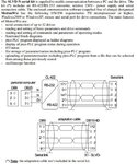
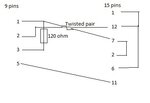
The following pictures are from the user guide of the servodrive:


And here is the manual itself:
https://divapps.parker.com/divapps/eme/EME/Literature_List/DOKUMENTATIONEN/sbc/manSLVDN_E5_GB.pdf
I hope you guys can help me out!
Edit:
Here is the data sheet of the rs485 converter:
https://www.ftdichip.com/Support/Documents/DataSheets/Modules/DS_USB-COM485-PLUS1.pdf
For my internship I need to make a serial communication between a servodrive with a 3 row 15 pins male output. It has a RS422/485 based protocol. In previous years the servo drive was able to communicate with a rs485 converter.
The communication link was like this : PC->(Via USB)RS485 converter (9pins male connector)->Self soldered connection wire -> RS485 15pins connection point.
But unfortunatly the cable between the converter and the (15 pins) serial output is nowhere to be found! and the colleague who made this doesn't work here anymore.
I have tried to solder it many times now, but I can't manage to get it fixed.
The following pictures are from the user guide of the servodrive:


And here is the manual itself:
https://divapps.parker.com/divapps/eme/EME/Literature_List/DOKUMENTATIONEN/sbc/manSLVDN_E5_GB.pdf
I hope you guys can help me out!
Edit:
Here is the data sheet of the rs485 converter:
https://www.ftdichip.com/Support/Documents/DataSheets/Modules/DS_USB-COM485-PLUS1.pdf
Last edited by a moderator:

