Continue to Site

Welcome to EDAboard.com

Welcome to our site! EDAboard.com is an international Electronics Discussion Forum focused on EDA software, circuits, schematics, books, theory, papers, asic, pld, 8051, DSP, Network, RF, Analog Design, PCB, Service Manuals... and a whole lot more! To participate you need to register. Registration is free. Click here to register now.

RS232 search received text

Status
Not open for further replies.
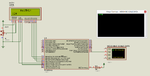
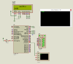
This is untested code using Serial Interrupt for receiving data.


Code C - [expand]
1
2
3
4
5
6
7
8
9
10
11
12
13
14
15
16
17
18
19
20
21
22
23
24
25
26
27
28
29
30
31
32
33
34
35
36
37
38
39
40
41
42
43
44
45
46
47
48
49
50
51
52
53
54
55
56
57
58
59
60
61
62
63
64
65
66
67
68
69
70
71
72
73
74
75
76
77
78
79
80
81
82
83
84
85
86
87
88
89
90
91
92
93
94
95
96
97
98
99
100
101
102
103
104
105
106
107
108
109
110
111
112
113
114
115
// LCD module connections
sbit LCD_RS at RB4_bit;
sbit LCD_EN at RB5_bit;
sbit LCD_D4 at RB0_bit;
sbit LCD_D5 at RB1_bit;
sbit LCD_D6 at RB2_bit;
sbit LCD_D7 at RB3_bit;
 
sbit LCD_RS_Direction at TRISB4_bit;
sbit LCD_EN_Direction at TRISB5_bit;
sbit LCD_D4_Direction at TRISB0_bit;
sbit LCD_D5_Direction at TRISB1_bit;
sbit LCD_D6_Direction at TRISB2_bit;
sbit LCD_D7_Direction at TRISB3_bit;
// End LCD module connections
 
char myFlags = 0;
char uart_rd[50], buffer[20], str[17];
unsigned int index = 0, i = 0, j = 0, value = 0;
 
sbit Read at myFlags.B0;
sbit Convert at myFlags.B1;
 
void interrupt() {
 
     if(OERR1_bit) {
     
            OERR1_bit = 0;
            CREN1_bit = 0;
            CREN1_bit = 1;
     }
     
     if(RC1IF_bit) {
          if(RC1REG == '=') {
                Read = 1;
                index = 0;
          }
          
          if(RC1REG == '0') {
                Read = 0;
                COnvert = 1;
          }
          
          if(Read) {
                uart_rd[index++] = RC1REG;          
          }
     
     
          RC1IF_bit = 0;
     }
}
 
void main() {
     
     CM1CON0 = 0x00;
     CM2CON0 = 0x00;
     
     SLRCON = 0x00;
     
     ANSELA = 0x00;
     ANSELB = 0x00;
     ANSELC = 0x00;
     
     TRISA = 0xC0;
     TRISB = 0x00;
     TRISC = 0xC0;
     
     PORTA = 0x00;
     PORTB = 0x00;
     PORTC = 0x00;
     
     LATA = 0x00;
     LATB = 0x00;
     LATC = 0x00;
     
     Lcd_Init();                        // Initialize LCD
     Lcd_Cmd(_LCD_CURSOR_OFF);          // Cursor off
     Lcd_Cmd(_LCD_CLEAR);               // Clear display
     
     Lcd_Out(1,6,"Weight:");                 // Write text in first row
 
     UART1_Init(9615);
     Delay_ms(100);
     
     RC1IE_bit = 1;
     PEIE_bit = 1;
     GIE_bit = 1;
     RC1IF_bit = 0;
          
     while(1) {
     
             if(Convert) {
             
                     i = 0;
                     j = 0;
                     while(uart_rd[i] != '0') {
                              buffer[j++] = uart_rd[i++];                   
                     }
                     
                     value = 0;
                     
                     for(i = 0; i < j; i++, j--) {
                            value += (buffer[i] - 48) * 10^(j - 1);                     
                     
                     }
                     
                     IntToStr(value, str);
                     Ltrim(str);
                     strcat(str, " Kgs");
                     Lcd_Out(2,6,str);
                     
                     Convert = 0;   
             }
     }
}


It is a strange format but I would do it this way:
Code:
char ValueFound = 0;
char RxByte;

if (UART1_Data_Ready()) RxByte = UART1_Read();

if(RxByte == '=') ValueFound = 1;

if((RxByte != '0') && (ValueFound == 1)
{
	Lcd_Out_Cp(RxByte );
	UART1_Write(RxByte); // and send data via UART
}
else ValueFound = 0;

This might include the '=' but it should only output characters up to the first '0'.
It would be even simpler if interrupts were used!

Please note that I have not tried it and I use a different compiler here.

Brian.
 

Change this


Code C - [expand]
1
value += (buffer[i] - 48) * 10^(j - 1);

to


Code C - [expand]
1
value += (buffer[i] - 48) * pow(10, (double)(j-1);


betwixt's code is better than mine. Use his code.

Here is the code which I made.


Working code attached.


Code C - [expand]
1
2
3
4
5
6
7
8
9
10
11
12
13
14
15
16
17
18
19
20
21
22
23
24
25
26
27
28
29
30
31
32
33
34
35
36
37
38
39
40
41
42
43
44
45
46
47
48
49
50
51
52
53
54
55
56
57
58
59
60
61
62
63
64
65
66
67
68
69
70
71
72
73
74
75
76
77
78
79
80
81
82
83
84
85
86
87
88
89
90
91
92
93
94
95
96
97
// LCD module connections
sbit LCD_RS at RB4_bit;
sbit LCD_EN at RB5_bit;
sbit LCD_D4 at RB0_bit;
sbit LCD_D5 at RB1_bit;
sbit LCD_D6 at RB2_bit;
sbit LCD_D7 at RB3_bit;
 
sbit LCD_RS_Direction at TRISB4_bit;
sbit LCD_EN_Direction at TRISB5_bit;
sbit LCD_D4_Direction at TRISB0_bit;
sbit LCD_D5_Direction at TRISB1_bit;
sbit LCD_D6_Direction at TRISB2_bit;
sbit LCD_D7_Direction at TRISB3_bit;
// End LCD module connections
 
char myFlags = 0;
char uart_rd[10] = "123000000", buffer[20], str[17];
unsigned int index = 0, i = 0, j = 0, value = 0;
 
sbit Read at myFlags.B0;
sbit Display at myFlags.B1;
 
void interrupt() {
 
     if(OERR1_bit) {
     
            OERR1_bit = 0;
            CREN1_bit = 0;
            CREN1_bit = 1;
     }
     
     if(RC1IF_bit) {
          if(RC1REG == '=') {
                Read = 1;
                index = 0;
          }
          
          if(RC1REG == '0') {
                Read = 0;
                Display = 1;                
          }
          
          if(Read) {
               uart_rd[index++] = RC1REG;
               uart_rd[index] = '\0';        
          }
     
     
          RC1IF_bit = 0;
     }
}
 
void main() {
     
     CM1CON0 = 0x00;
     CM2CON0 = 0x00;
     
     SLRCON = 0x00;
     
     ANSELA = 0x00;
     ANSELB = 0x00;
     ANSELC = 0x00;
     
     TRISA = 0xC0;
     TRISB = 0x00;
     TRISC = 0xC0;
     
     PORTA = 0x00;
     PORTB = 0x00;
     PORTC = 0x00;
     
     LATA = 0x00;
     LATB = 0x00;
     LATC = 0x00;
     
     Lcd_Init();                        // Initialize LCD
     Lcd_Cmd(_LCD_CURSOR_OFF);          // Cursor off
     Lcd_Cmd(_LCD_CLEAR);               // Clear display
     
     Lcd_Out(1,6,"Weight:");                 // Write text in first row
 
     UART1_Init(9615);
     Delay_ms(100);
     
     RC1IE_bit = 1;
     PEIE_bit = 1;
     GIE_bit = 1;
     RC1IF_bit = 0;
          
     while(1) {
            if(Display) {
                  LCD_Out(2,1,uart_rd);
                  Display = 0;           
            }     
     }
}


Attachments

  • uart2lcd.rar
    113 KB · Views: 44
  • weigh scale data.png
    weigh scale data.png
    51.3 KB · Views: 67
Last edited:

It is a strange format but I would do it this way:

Our code will probably work the same. My code is strange because I'm not a software engineer. I also don't use MikroC, I only toy with it.
We both mixed literals with text, it might need to be corrected. The Lcd_Out_Cp puts text at the cursor and after reaching the end of line the data is lost, so it needs correcting too. Well, we have to leave some for him to do.
 

If you still want the integer value to do some calculation then you can do like this.


Code C - [expand]
1
value = atoi(uart_rd);


Thanks a lot for your help to both of you, I will test it in hardware then report back to you.
 

Here is a better code than my previous code.


Code C - [expand]
1
2
3
4
5
6
7
8
9
10
11
12
13
14
15
16
17
18
19
20
21
22
23
24
25
26
27
28
29
30
31
32
33
34
35
36
37
38
39
40
41
42
43
44
45
46
47
48
49
50
51
52
53
54
55
56
57
58
59
60
61
62
63
64
65
66
67
68
69
70
71
72
73
74
75
76
77
78
79
80
81
82
83
84
85
86
87
88
89
90
91
92
93
94
95
96
// LCD module connections
sbit LCD_RS at RB4_bit;
sbit LCD_EN at RB5_bit;
sbit LCD_D4 at RB0_bit;
sbit LCD_D5 at RB1_bit;
sbit LCD_D6 at RB2_bit;
sbit LCD_D7 at RB3_bit;
 
sbit LCD_RS_Direction at TRISB4_bit;
sbit LCD_EN_Direction at TRISB5_bit;
sbit LCD_D4_Direction at TRISB0_bit;
sbit LCD_D5_Direction at TRISB1_bit;
sbit LCD_D6_Direction at TRISB2_bit;
sbit LCD_D7_Direction at TRISB3_bit;
// End LCD module connections
 
char myFlags = 0;
char uart_rd[10] = "123000000", buffer[20], str[17];
unsigned int index = 0, i = 0, j = 0, value = 0;
 
sbit Read at myFlags.B0;
sbit Display at myFlags.B1;
 
void interrupt() {
 
     if(OERR1_bit) {
     
            OERR1_bit = 0;
            CREN1_bit = 0;
            CREN1_bit = 1;
     }
     
     if(RC1IF_bit) {
          if((RC1REG != '0') && (Read == 1))  {
                  uart_rd[index++] = RC1REG;
                  uart_rd[index] = '\0'; 
                               
          }
          else if(RC1REG == '=') {
                Read = 1;
                index = 0;
          }          
          else if(RC1REG == '0') {
                 Display = 1;
          }
           
          RC1IF_bit = 0;
     }
}
 
void main() {
     
     CM1CON0 = 0x00;
     CM2CON0 = 0x00;
     
     SLRCON = 0x00;
     
     ANSELA = 0x00;
     ANSELB = 0x00;
     ANSELC = 0x00;
     
     TRISA = 0xC0;
     TRISB = 0x00;
     TRISC = 0xC0;
     
     PORTA = 0x00;
     PORTB = 0x00;
     PORTC = 0x00;
     
     LATA = 0x00;
     LATB = 0x00;
     LATC = 0x00;
     
     Lcd_Init();                        // Initialize LCD
     Lcd_Cmd(_LCD_CURSOR_OFF);          // Cursor off
     Lcd_Cmd(_LCD_CLEAR);               // Clear display
     
     Lcd_Out(1,6,"Weight:");                 // Write text in first row
 
     UART1_Init(9615);
     Delay_ms(100);
     
     RC1IE_bit = 1;
     PEIE_bit = 1;
     GIE_bit = 1;
     RC1IF_bit = 0;
          
     while(1) {
            if(Display) {
                  LCD_Out(2,1,uart_rd);
                  Display = 0;           
            }
            
            value = atoi(uart_rd);     
     }
}


It seems that neither PIC16F877 nor PIC18F452/0 SUPPORT serial interrupt, I couldn't test this code since I don't have the PIC used in compiling and it's not available where I live

- - - Updated - - -

It is a strange format but I would do it this way:
Code:
char ValueFound = 0;
char RxByte;

if (UART1_Data_Ready()) RxByte = UART1_Read();

if(RxByte == '=') ValueFound = 1;

if((RxByte != '0') && (ValueFound == 1)
{
	Lcd_Out_Cp(RxByte );
	UART1_Write(RxByte); // and send data via UART
}
else ValueFound = 0;

This might include the '=' but it should only output characters up to the first '0'.
It would be even simpler if interrupts were used!

Please note that I have not tried it and I use a different compiler here.

Brian.

It didn't work, Once I enter = sign it keeps writing the same sign on screen and don't get the numbers after

here is the code

Code:
sbit LCD_RS at RB1_bit;
sbit LCD_EN at RB0_bit;
sbit LCD_D4 at RB4_bit;
sbit LCD_D5 at RB5_bit;
sbit LCD_D6 at RB6_bit;
sbit LCD_D7 at RB7_bit;

sbit LCD_RS_Direction at TRISB1_bit;
sbit LCD_EN_Direction at TRISB0_bit;
sbit LCD_D4_Direction at TRISB4_bit;
sbit LCD_D5_Direction at TRISB5_bit;
sbit LCD_D6_Direction at TRISB6_bit;
sbit LCD_D7_Direction at TRISB7_bit;
// End LCD module connections
int i;
char txt1[] = "=test";
char receive[20];
char uart_rd; 
void main() 
{ 

  Lcd_Init();                        // Initialize LCD

  Lcd_Cmd(_LCD_CLEAR);               // Clear display
  Lcd_Cmd(_LCD_CURSOR_OFF);          // Cursor off
  Lcd_Out(1,6,txt1);                 // Write text in first row


UART1_Init(9600); // Initialize UART module at 9600 bps 
Delay_ms(100); // Wait for UART module to stabilize 
UART1_Write_Text("Start"); 
UART1_Write(10); 
UART1_Write(13); 
while (1) 
{ // Endless loop 
              
      char ValueFound = 0;
char RxByte;

if (UART1_Data_Ready()) RxByte = UART1_Read();

if(RxByte == '=') {ValueFound = 1;} else {ValueFound = 0;}
 delay_ms(10);
if((RxByte != '0') && (ValueFound == 1))
{
	Lcd_Out_Cp(RxByte );
	UART1_Write(RxByte); // and send data via UART
}


 } }
 

You have missed my code on post #20 , it shouldn't get stuck displaying =
 

It seems that neither PIC16F877 nor PIC18F452/0 SUPPORT serial interrupt
ALL PICs support serial interrupt. Show me where you found this wrong information.

If you use interrupts it makes life much easier, you can write a simple routine that is called each time a character arrives at the UART, there is no need to keep looking to see if the UART is ready and you do not need the loops which hold up the rest of the program. There is a real danger at the moment that while doing other things, for example writing to the LCD, you miss an incoming character altogether. With interrupts that doesn't happen.

I should add that the changes you made to my code are guaranteed to stop it working!

Brian.
 

ALL

I should add that the changes you made to my code are guaranteed to stop it working!

Brian.

Hi Brian,
kobre98 missed the else condition in your code, this is why the = is repeated.
Look carefully at your code, it lets displaying the = as it appears in the uart. What is missing is waiting for the next uart input and displaying it if it isn't zero.
I also didn't notice this problem when I looked at your code.
I'm sure you can fix it.
 

Did you try this code ?


Code C - [expand]
1
2
3
4
5
6
7
8
9
10
11
12
13
14
15
16
17
18
19
20
21
22
23
24
25
26
27
28
29
30
31
32
33
34
35
36
37
38
39
40
41
42
43
44
45
46
47
48
49
50
51
52
53
54
55
56
57
58
59
60
61
62
63
64
65
66
67
68
69
70
71
72
73
74
75
76
77
78
79
80
81
82
83
84
85
86
87
88
89
90
91
92
93
94
95
96
// LCD module connections
sbit LCD_RS at RB4_bit;
sbit LCD_EN at RB5_bit;
sbit LCD_D4 at RB0_bit;
sbit LCD_D5 at RB1_bit;
sbit LCD_D6 at RB2_bit;
sbit LCD_D7 at RB3_bit;
 
sbit LCD_RS_Direction at TRISB4_bit;
sbit LCD_EN_Direction at TRISB5_bit;
sbit LCD_D4_Direction at TRISB0_bit;
sbit LCD_D5_Direction at TRISB1_bit;
sbit LCD_D6_Direction at TRISB2_bit;
sbit LCD_D7_Direction at TRISB3_bit;
// End LCD module connections
 
char myFlags = 0;
char uart_rd[10], buffer[20], str[17];
unsigned int index = 0, value = 0;
 
sbit Read at myFlags.B0;
sbit Display at myFlags.B1;
 
void interrupt() {
 
     if(OERR1_bit) {
     
            OERR1_bit = 0;
            CREN1_bit = 0;
            CREN1_bit = 1;
     }
     
     if(RC1IF_bit) {
          if((RC1REG != '0') && (Read))  {
                  uart_rd[index++] = RC1REG;
                  uart_rd[index] = '\0'; 
                               
          }
          else if(RC1REG == '=') {
                Read = 1;
                index = 0;
          }          
          else if(RC1REG == '0') {
                 Display = 1;
          }
           
          RC1IF_bit = 0;
     }
}
 
void main() {
     
     CM1CON0 = 0x00;
     CM2CON0 = 0x00;
     
     SLRCON = 0x00;
     
     ANSELA = 0x00;
     ANSELB = 0x00;
     ANSELC = 0x00;
     
     TRISA = 0xC0;
     TRISB = 0x00;
     TRISC = 0xC0;
     
     PORTA = 0x00;
     PORTB = 0x00;
     PORTC = 0x00;
     
     LATA = 0x00;
     LATB = 0x00;
     LATC = 0x00;
     
     Lcd_Init();                        // Initialize LCD
     Lcd_Cmd(_LCD_CURSOR_OFF);          // Cursor off
     Lcd_Cmd(_LCD_CLEAR);               // Clear display
     
     Lcd_Out(1,6,"Weight:");                 // Write text in first row
 
     UART1_Init(9615);
     Delay_ms(100);
     
     RC1IE_bit = 1;
     PEIE_bit = 1;
     GIE_bit = 1;
     RC1IF_bit = 0;
          
     while(1) {
            if(Display) {
                  LCD_Out(2,1,uart_rd);
                  Display = 0;           
            }
            
            value = atoi(uart_rd);     
     }
}


- - - Updated - - -

You didn't tell what happens if weight is 40 or 400 kgs. It will get displayed as 4 kgs.
 

Vbase, I intended the new code to be a drop in for the code inside the while() loop in the original. It would still have one deficiency, it would stop on the first zero character even if it was between other digits.

The best way is to use interrupts, capture everything between each '=' to a buffer, trim all the trailing zero characters (like Ltrim but using '0' instead of spaces) then convert the result to a number. I can write it easily in my compiler but Mikro is not fully ISO compliant and it has some strange library functions. I'm not sure how portable it would be.

Brian.
 

Did you try this code ?


Code C - [expand]
1
2
3
4
5
6
7
8
9
10
11
12
13
14
15
16
17
18
19
20
21
22
23
24
25
26
27
28
29
30
31
32
33
34
35
36
37
38
39
40
41
42
43
44
45
46
47
48
49
50
51
52
53
54
55
56
57
58
59
60
61
62
63
64
65
66
67
68
69
70
71
72
73
74
75
76
77
78
79
80
81
82
83
84
85
86
87
88
89
90
91
92
93
94
95
96
// LCD module connections
sbit LCD_RS at RB4_bit;
sbit LCD_EN at RB5_bit;
sbit LCD_D4 at RB0_bit;
sbit LCD_D5 at RB1_bit;
sbit LCD_D6 at RB2_bit;
sbit LCD_D7 at RB3_bit;
 
sbit LCD_RS_Direction at TRISB4_bit;
sbit LCD_EN_Direction at TRISB5_bit;
sbit LCD_D4_Direction at TRISB0_bit;
sbit LCD_D5_Direction at TRISB1_bit;
sbit LCD_D6_Direction at TRISB2_bit;
sbit LCD_D7_Direction at TRISB3_bit;
// End LCD module connections
 
char myFlags = 0;
char uart_rd[10], buffer[20], str[17];
unsigned int index = 0, value = 0;
 
sbit Read at myFlags.B0;
sbit Display at myFlags.B1;
 
void interrupt() {
 
     if(OERR1_bit) {
     
            OERR1_bit = 0;
            CREN1_bit = 0;
            CREN1_bit = 1;
     }
     
     if(RC1IF_bit) {
          if((RC1REG != '0') && (Read))  {
                  uart_rd[index++] = RC1REG;
                  uart_rd[index] = '\0'; 
                               
          }
          else if(RC1REG == '=') {
                Read = 1;
                index = 0;
          }          
          else if(RC1REG == '0') {
                 Display = 1;
          }
           
          RC1IF_bit = 0;
     }
}
 
void main() {
     
     CM1CON0 = 0x00;
     CM2CON0 = 0x00;
     
     SLRCON = 0x00;
     
     ANSELA = 0x00;
     ANSELB = 0x00;
     ANSELC = 0x00;
     
     TRISA = 0xC0;
     TRISB = 0x00;
     TRISC = 0xC0;
     
     PORTA = 0x00;
     PORTB = 0x00;
     PORTC = 0x00;
     
     LATA = 0x00;
     LATB = 0x00;
     LATC = 0x00;
     
     Lcd_Init();                        // Initialize LCD
     Lcd_Cmd(_LCD_CURSOR_OFF);          // Cursor off
     Lcd_Cmd(_LCD_CLEAR);               // Clear display
     
     Lcd_Out(1,6,"Weight:");                 // Write text in first row
 
     UART1_Init(9615);
     Delay_ms(100);
     
     RC1IE_bit = 1;
     PEIE_bit = 1;
     GIE_bit = 1;
     RC1IF_bit = 0;
          
     while(1) {
            if(Display) {
                  LCD_Out(2,1,uart_rd);
                  Display = 0;           
            }
            
            value = atoi(uart_rd);     
     }
}


- - - Updated - - -

You didn't tell what happens if weight is 40 or 400 kgs. It will get displayed as 4 kgs.

After hitting compile I get these messages

26 324 Undeclared identifier 'OERR1_bit' in expression MyProject.c
28 324 Undeclared identifier 'OERR1_bit' in expression MyProject.c
29 324 Undeclared identifier 'CREN1_bit' in expression MyProject.c
30 324 Undeclared identifier 'CREN1_bit' in expression MyProject.c
33 324 Undeclared identifier 'RC1IF_bit' in expression MyProject.c
34 324 Undeclared identifier 'RC1REG' in expression MyProject.c
35 324 Undeclared identifier 'RC1REG' in expression MyProject.c
39 324 Undeclared identifier 'RC1REG' in expression MyProject.c
43 324 Undeclared identifier 'RC1REG' in expression MyProject.c
47 324 Undeclared identifier 'RC1IF_bit' in expression MyProject.c
53 324 Undeclared identifier 'CM1CON0' in expression MyProject.c
54 324 Undeclared identifier 'CM2CON0' in expression MyProject.c
56 324 Undeclared identifier 'SLRCON' in expression MyProject.c
58 324 Undeclared identifier 'ANSELA' in expression MyProject.c
59 324 Undeclared identifier 'ANSELB' in expression MyProject.c
60 324 Undeclared identifier 'ANSELC' in expression MyProject.c
70 324 Undeclared identifier 'LATA' in expression MyProject.c
71 324 Undeclared identifier 'LATB' in expression MyProject.c
72 324 Undeclared identifier 'LATC' in expression MyProject.c
83 324 Undeclared identifier 'RC1IE_bit' in expression MyProject.c
86 324 Undeclared identifier 'RC1IF_bit' in expression MyProject.c
0 102 Finished (with errors): 26 Apr 2015, 18:36:10 MyProject.mcppi
 

Yes, you get that error because you are using a different PIC than the one I used. I used PIC18F26K22. It has 2 UART. Your PIC has only one UART. So you have to use these

Code:
OERR_bit
CREN_bit
RCIF_bit
RCREG
RCIE_bit
and

if you are using PIC16F then replace LATx with PORTx

Also for your PIC maybe there is ANSEL / ANSELH / CMCON / ADCON1. So, if you zip and post your complete mikroC project then I will fix the code according to your PIC by looking at the datasheet.

You can also set the proper registers. All you have to do is disable comparators (not needed for your project) and make all IO pins as digital IO.
 

This is in addition to your code.
It reads every char that comes in and if it isn't 0 after the = it puts it on the LCD and sends it to UART.

Code:
// LCD module connections
sbit LCD_RS at RB0_bit;
sbit LCD_EN at RB1_bit;
sbit LCD_D4 at RB4_bit;
sbit LCD_D5 at RB5_bit;
sbit LCD_D6 at RB6_bit;
sbit LCD_D7 at RB7_bit;

sbit LCD_RS_Direction at TRISB0_bit;
sbit LCD_EN_Direction at TRISB1_bit;
sbit LCD_D4_Direction at TRISB4_bit;
sbit LCD_D5_Direction at TRISB5_bit;
sbit LCD_D6_Direction at TRISB6_bit;
sbit LCD_D7_Direction at TRISB7_bit;
// End LCD module connections

char txt1[] = "=test";

char uart_rd; 
void main() 
{ 

  Lcd_Init();                        // Initialize LCD

  Lcd_Cmd(_LCD_CLEAR);               // Clear display
  Lcd_Cmd(_LCD_CURSOR_OFF);          // Cursor off
  Lcd_Out(1,6,txt1);                 // Write text in first row


UART1_Init(9600); // Initialize UART module at 9600 bps 
Delay_ms(100); // Wait for UART module to stabilize 
UART1_Write_Text("Start"); 
UART1_Write(10); 
UART1_Write(13); 
while (1) 
{ // Endless loop 

if (UART1_Data_Ready()) { // If data is received, 
uart_rd = UART1_Read(); // read the received data,
if(uart_rd=='='){
     if (UART1_Data_Ready()) { // If data is received, 
     uart_rd = UART1_Read(); // read the received data,
          if(uart_rd){             //if digit after = not zero  
              Lcd_Out_Cp(uart_rd); 
              UART1_Write(uart_rd); // and send data via UART
          }
     }
 } } }

It didn't work either ! it displayed nothing on LCD except for the test word

as in the attached image 1.JPG

- - - Updated - - -

Yes, you get that error because you are using a different PIC than the one I used. I used PIC18F26K22. It has 2 UART. Your PIC has only one UART. So you have to use these

Code:
OERR_bit
CREN_bit
RCIF_bit
RCREG
RCIE_bit
and

if you are using PIC16F then replace LATx with PORTx

Also for your PIC maybe there is ANSEL / ANSELH / CMCON / ADCON1. So, if you zip and post your complete mikroC project then I will fix the code according to your PIC by looking at the datasheet.

You can also set the proper registers. All you have to do is disable comparators (not needed for your project) and make all IO pins as digital IO.

attached my test
 

Attachments

  • eda.zip
    38.9 KB · Views: 32

Fixed code attached.
 

Attachments

  • eda.rar
    76.6 KB · Views: 34
  • weighing.png
    weighing.png
    46.8 KB · Views: 66

Vbase, I intended the new code to be a drop in for the code inside the while() loop in the original. It would still have one deficiency, it would stop on the first zero character even if it was between other digits.

The best way is to use interrupts, capture everything between each '=' to a buffer, trim all the trailing zero characters (like Ltrim but using '0' instead of spaces) then convert the result to a number. I can write it easily in my compiler but Mikro is not fully ISO compliant and it has some strange library functions. I'm not sure how portable it would be.

Brian.

Brian,
That is right MicroC isn't portable. They use libraries for everything to make it easy to write a code, of course libraries have limited options. If you compile with it a code that was written in MPLAB for MCC18 you get only a few errors.
Using interrupt is a little complicated for beginners but it is ok if they write imperfect code.
 

Fixed code attached.

Thanks a lot, I tested this code using Proteus and hardware, in Proteus everything works fine, but when I turn to hardware since I receive continuous non stop feed of this format =000240=000090=000088= ...etc
It display things very fast on the LCD in such a way that it display unknown characters, I want this code to display 10 or 20 reading then stop getting readings.

It's not just one value, and it doesn't depend on zeros I need it to read the value between the two "=" signs, and display it on LCD.
 

It display things very fast on the LCD in such a way that it display unknown characters, I want this code to display 10 or 20 reading then stop getting readings.

LCDs tend to be very slow devices compared to the execution speed of modern microcontrollers so one requires delays between writing characters otherwise it displays rubbish
for example, on a Bytronic PIC24 trainer
**broken link removed**
using a PIC24FJ256GB110 I find the following works OK
Code:
void lcdNibble(int n)
{
    int lcd=LCDdata;
//	lcd_delay();
	__delay_us(800); 
  	LCDdata = (lcd&0xfff0) | ((n & 0x0f));			// send out lower Nibble
	//lcd_delay();
// 	__delay_us(1); 
  	Nop();					// Wait E Pulse width time (min 230ns)
	Nop();
	Nop();
	Nop();
	Nop();
	Nop();
	Nop();
	Nop();
	Nop();

  LCDstatus.E=1;					// take clock E high 
// 	__delay_us(1); 
	Nop();					// Wait E Pulse width time (min 230ns)
	Nop();
	Nop();
	Nop();
	Nop();
	Nop();
	Nop();
	Nop();
	Nop();

	//lcd_delay();
    LCDstatus.E=0;
 	__delay_us(800); 
	//lcd_delay();
 }
note the delay when changing the enable pulse level and the 800 microseconds delay at the end of the function (before attempting to write the following character)
the delay values will depend on the LCD and processor execution speed and in practice one has to try values until it works Ok with the minimum delay
 

Status
Not open for further replies.

Similar threads

Part and Inventory Search

Welcome to EDABoard.com

Sponsor

Back
Top