Continue to Site

Welcome to EDAboard.com

Welcome to our site! EDAboard.com is an international Electronics Discussion Forum focused on EDA software, circuits, schematics, books, theory, papers, asic, pld, 8051, DSP, Network, RF, Analog Design, PCB, Service Manuals... and a whole lot more! To participate you need to register. Registration is free. Click here to register now.

[SOLVED] RS232 full with Max3243

Status
Not open for further replies.

reza147

Member level 1
Joined
May 9, 2013
Messages
34
Helped
3
Reputation
6
Reaction score
3
Trophy points
1,288
Activity points
1,594
Hello
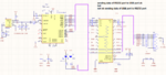
We design USB to RS232 Full with Ft232 and MAX3243, But this converter does not work properly!

This converter receives serial data 232 correctly, and transmits it to the computer on its USB side.
But when we send data to the serial via USB of this converter, we do not have this data converter on the serial port side!
That is, the chip Max3243 takes the data from the serial side correctly and gives it to Ft232. But it does not pass Ft232 data properly to the serial port.

I have attached a schematic, please look. Tell me if you find something.
thanks
 

Attachments

  • 232f.png
    232f.png
    158.8 KB · Views: 369

All the capacitors around the MAX should be 100nF. 470pF is far too small for the charge pumps that generate the RS232 side voltages to use.

Other points:
I can't see what C8 & C17 is supposed to do.
There are references to 'GND485' around P1. Are these the same ground as the rest of the circuit? (they should be!)
Are you using RS232 or RS485 protocols?


Brian.
 
Last edited:

    reza147

    Points: 2
    Helpful Answer Positive Rating
Hi Brian.
Thanks for your answer.
Ok. we change the capacitor 470pf to 100nf. And we will test again.

This value of 470pf in Max's own document.

C8 & C17 are for better power supply of ICs. we can change 47pf to 10nf.

we have a resistance of 100 ohm between GND_circuit and GND_external_device_RS232 (P1).We set this resistance to 232 for ground adaptation. (adaptation beetwen this converter and external device 232).
We only have this circuit. And we do not have 485 for this converter. 'GND485' is just a name.

S.rezapoor
 

Hi
This value of 470pf in Max's own document
No. I can't find this.
Even on the first page of the datasheet they say: "External Capacitors: 4 × 0.1 μF"

47pF for stabilizing power supply is way too low.
FTDI recommends 4.7uF.
(You need to parallel 100.000 pieces of 47pF to get 4.7uF).

Maybe you confuse the letters. (f-p-n-u-m-[none]-k-M-G)
1pF
1000pF = 1nF
1000nF = 1uF
1000uF = 1mF
1000mF = 1F

Klaus
 

    reza147

    Points: 2
    Helpful Answer Positive Rating
Hi
Thanks of Dear Brian, Klaus, FvM and edaboard group.
Yes. I was wrong in calculating the Capacitors.

We changed the value of capacitor C21_100nf, C22.23.24_470nf: Now our converter has correct sending and receiving.
Our problem is solved.

We have a '10uf tantalum power supply' capacitor and a 'USB TVS' diode in the schematic, but we temporarily removed it so that the schematic would not be crowded.

S.Rezapoor
 

Hi
If i use 1uf for C21.22.23.24 is better?
Of course Capacitor 1uf more expensive, But if better function the high price is not a problem for us.
 

Hi,

I see no benefit. Just keep on the datasheet values and you are safe.

Klaus
 

Status
Not open for further replies.

Similar threads

Part and Inventory Search

Welcome to EDABoard.com

Sponsor

Back
Top