Continue to Site

Welcome to EDAboard.com

Welcome to our site! EDAboard.com is an international Electronics Discussion Forum focused on EDA software, circuits, schematics, books, theory, papers, asic, pld, 8051, DSP, Network, RF, Analog Design, PCB, Service Manuals... and a whole lot more! To participate you need to register. Registration is free. Click here to register now.

routing for multi drop bi-directional bus??

Status
Not open for further replies.

s3034585

Full Member level 4
Joined
May 24, 2004
Messages
226
Helped
1
Reputation
2
Reaction score
0
Trophy points
1,296
Activity points
2,087
multi drop bus termination

Hi Guys

i have a dought about routing multi drop bi-directional bus. can some pls share there view on this.

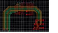
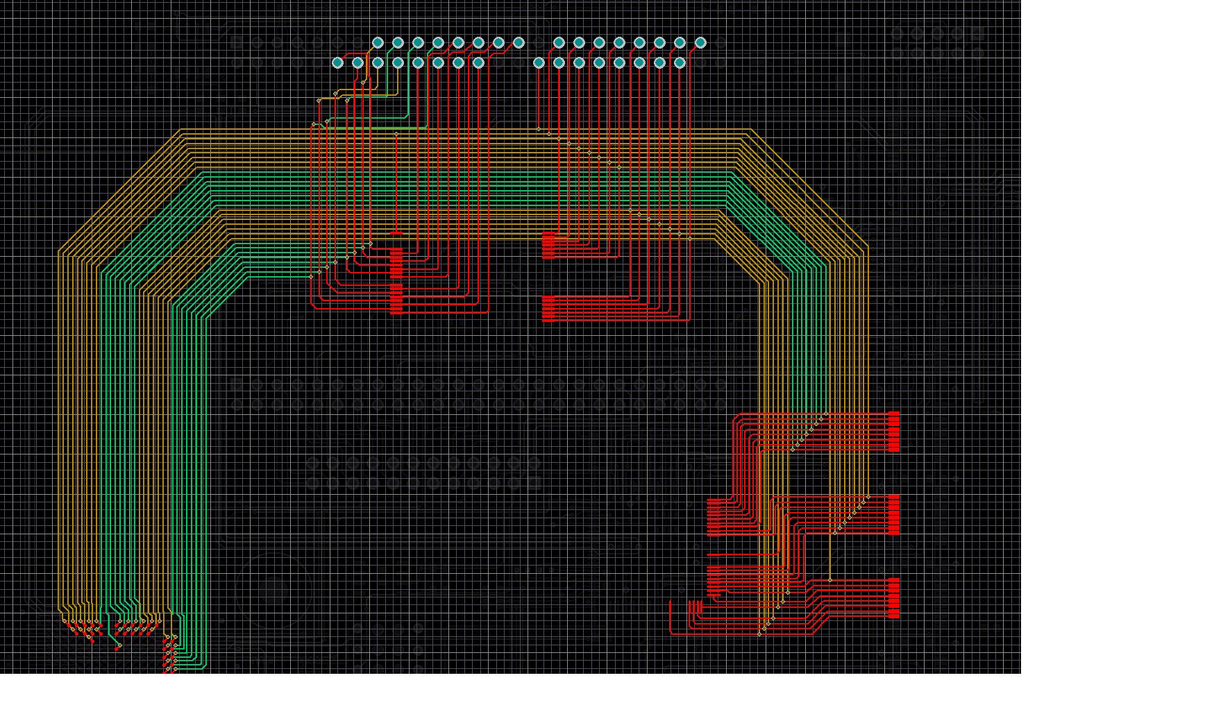
my current project pcb is 6 layers and contains 2 processors, fpga, 2 cpld's. each channel has a processor and cpld. i am trying to route add and data bus between processor- cpld -fpga-back plane connector. is it a good idea to tap the trace to vias form all the four side(in diff layers). like a plus sign with a device at each end of the trace. the placement of the components is the reason for this kind of routing.

can some pls share there view on it

thanks in advance
tama
][/img]
 

termination bidirectional multi drop

The link below describes the types of routing techniques and the advantages of each topology.

https://www.altera.com/literature/an/an224.pdf

If you are using Star topology than you have to match lengths beetween all the traces meeting at the main VIA and also use termenations (if required) at all the ends.

In daisy chain u dont need to do length mating for the same line but has to be done in a group and only one termination may require which is placed at the end.
 

pcb routing multi-drop

Hi v_kumar

Thanks for the info.. as u have mentioned that star topology needs matching of lenghts. does it mean that the lenght on all the four sides should be exactly identical or the lenght of all the tracks on the same side should be identical. where can i get more info about this.

thanks
tama
 

If I understand right, the bus has further extensions through the connector. If so, the bus should be analyzed as a whole, also including cable connected segments. Depending on the length of this additional segments, routing of the shown part may be minor problem compared to the rest.

I guess, that the bus uses a basically unterminated IO standard as LVTTL/LVCMOS. In this case, any possible multi drop topology is a combination of impedance mismatchings of varying severity. This may be tolerable for geometrical small busses and completely fail for too long ones. Partial termination of longer bus stubs with C coupled "end resistors" or introduction of small series resistors at stub turn-off may be a means to reduce line reflections to a suitable level. But such mesures always have to adapted to a given topology.

P.S.: Please notice, that the said AN224 is mainly discussing clock routing topologies, which is a comparatively simple task. When discussing multi-drop bus-alike topologies (in other documents), Altera usually refers to teminated IO standards.
 

Hi FvM

Thanks for your reply.. the connector what you see in the image is actually a processor module from where the bus starts. on the left hand side of the connector we have fpga and on the right hand side a CPLD and level translator... which in turn feeds to a back panel connector. and in the centre just below the connector we have flash. at present we havent done the simulations hence we havent added terminations...

my comp. dosnt have a separate simulation software. We just have altium designer and intend to use the inbuild simulator from it.


thanks
tama
 

If you are using STAR topology than from the point (main junction ) where you are splitting to all the components must be lenght matched and if terminations are used than it will be required on all the segments else that segment will not be length matched.
 

I think, a basic transmission line model with load capacitances and driver impedance would be suitable to check expectable signal quality with the design. As already said, I understand that you have a typical data bus that can't operate fully terminated. Termination in this regard only would mean taking measures to reduce reflections by some amount.

In an unterminated situation, no general rules exist for arrangement of bus segments or stubs. Reducing the total trace length is probably most important. If any node is a potential driver to the bus, no equal length consideration is applicable at all.
 

Hi FvM
Can you upload any document which explains the termination for IO Buses.

If trace length cannot be decreased or cannot be kept minimum what do you suggest to be done in the bi-direction bus situations.
 

Status
Not open for further replies.

Part and Inventory Search

Welcome to EDABoard.com

Sponsor

Back
Top