Continue to Site

Welcome to EDAboard.com

Welcome to our site! EDAboard.com is an international Electronics Discussion Forum focused on EDA software, circuits, schematics, books, theory, papers, asic, pld, 8051, DSP, Network, RF, Analog Design, PCB, Service Manuals... and a whole lot more! To participate you need to register. Registration is free. Click here to register now.

[SOLVED] Rotating LED Globe Project

Status
Not open for further replies.

osa1313

Junior Member level 3
Joined
Jan 1, 2012
Messages
25
Helped
0
Reputation
0
Reaction score
0
Trophy points
1,281
Activity points
1,459
Hi i am new to this forum and i found this youtube video. I followed the links in the description and got to this site
1. Rotating LED Globe - Hacked Gadgets – DIY Tech Blog
and also found this one
2. DIY Spinning LED Globe Build Log - Hacked Gadgets – DIY Tech Blog
and this one
3. Arduino based Rotating POV Globe - Hacked Gadgets – DIY Tech Blog

And i thought that i would like to make a similar one or just about same one like in the LINK 2 and LINK 3.
But when i translated the text in LINK 2 it wasn't very good so i tried to find some info on the LINK 1 but the schematics i didn't understand very well also the code is unavailable.
On the LINK 3 i really liked the effects but i didn't find much information or schematics.
So i found this schematics. But there is few parts missing to it like the optocoupler open (I am not sure if it's the right word for this part as i had to translate it of another site basically what i mean is to add this component so the processor knows the spinning speed of the globe)And then i would need to make a code for the globe on what i want it to display where in my case it is a globe. So maybe someone on this forum made led globe and can help me with the schematics and the code. Thank You For Help.
http://obrazki.elektroda.pl/64_1274869349.png
 
Last edited:
The device in link 2 appears to be completely different from the ones in links 1 and 3. Possibly a fixed sphere instead of a virtual one?

---------- Post added at 21:57 ---------- Previous post was at 21:40 ----------

Oh, wait. Also a virtual sphere. The video didn't show it not rotating, but there are other photos of it not in motion, so you can see how it is constructed physically. Unlike the other two, the LEDs are visible from the inside as well as the outside.

---------- Post added at 22:27 ---------- Previous post was at 21:57 ----------

I'm curious how power gets to the LEDs, and how it gets sorted out. Can all 32 be lit at a given instant, or just one?

I did notice that the globe in LINK 2 is made in a sort of a C shape and in LINK 3 And LINK 1 it is a sphere.
I would like to show two sides of the globe not just one and by looking at the videos all three of the globes show whole globe at once.
I am not sure how the power gets to the LEDs but i think they are all connected by solder and a the bottom of the sphere or like in the link 2 C shape there is a cable connected to the pcb you can see this in this picture but i am wondering how to power gets to the LEDs in the LINK 2 there is a cable draw on the picture 2.
I was wondering when the globe spins you can see a black line passing on it in LINK 1 and LINK 3 where in the LINK 2 there is no black line so i was thinking if wouldn't be better to make a globe like they did in the LINK2?

1. http://hackedgadgets.com/wp-content/uploads/2011/10/arduino-based-rotating-pov-globe_2.jpg

2. http://easyelectronics.ru/img/readydev/led_globe/riko0.jpeg
 

I suspect the units in link 1 and 3 are built around VCR head-drum assemblies. That's how I'd do it if I were building one, since the problem of communicating with the rotating elements has already been solved there. Notice the circuit boards mounted on the rings of both of those units, which are there to decode the data as to which LEDs should be lit at a given moment.

I think the black line you mention is just the dark side of the ring. The video for link 2 was shot in the dark, so you don't see the back of the ring passing in front of anything.
 

At last i made my decision that my globe will be like the one in LINK 2 Google TBumacz.
But i need some info if the AVR Attiny is AVR ATTINY13A-SSU or different AVR ATTINY and what is the difference between the ATTINY13A-PU and ATTINY13A-SSU ?
Also can somebody workout how the LEDs are connected and what are these pink cables from the resistor where are they meant to be connected ?
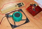
Does anybody know what type of LEDs they used in LINK 2 . The globe in LINK 2 is rotated by a Rotary transformer threw which electricity is passed threw to the PCB and LEDs. Also could someone tell me what are these circled in red pen pcb used for ? I got the picture from LINK 2. riko2.jpg Bez tytułu.png
 
Last edited:

Sorry for my previous stupid questions but at the time when i was posting i didn't have a clue about electronic but now after readying couple of good books i understand everything and will be posting my finished globe hopefully soon.
 

Status
Not open for further replies.

Part and Inventory Search

Welcome to EDABoard.com

Sponsor

Back
Top