Welcome to our site! EDAboard.com is an international Electronics Discussion Forum focused on EDA software, circuits, schematics, books, theory, papers, asic, pld, 8051, DSP, Network, RF, Analog Design, PCB, Service Manuals... and a whole lot more! To participate you need to register. Registration is free. Click here to register now.
hi
i think u r problem has not be solved yet. But anyways i hope that u r making all the basic things correct like ur gain , swing ,initial condition. Bt if still u r not getting the result. I must suggest you that u analytical calculate the frequency of ur circuit and then realize the circuit. I simply means u r problem will be solved by using a 11stage oscillator i suppose. It could be the case also that it will work well with 9 or 7 stage oscillator but for that u need to know the freq . make the 11 stages oscillator for SCl and u ll be able to see u r oscillations.
If you look at the first image you sent, you can see that there is an oscillation that is trying to start but it is triangular. Therefore, one of the following things may be happening:
1) your accuracy specs are too loose. Use conservative setting, and default Itol, reltol and vtol.
2) You are heavily slew-rate limitted. This means you have either too much capacitive load or not enough current setting.
3) Insufficient gain in the loop so you are very slowly increasing the oscillation.
The gain of the output stage is gm*Rout. Your PMOS is definetally sized for a good Rout, but your NMOS is not. You may be too worried about slew rate and made your MOS wide, but instead you increased the capacitive load too much, lowered the output gain too much due to the low Rout of the NMOS and killed your gain. Try reducing the width of the NMOS by at least 5X and see what happens.
The other problem I see is that an oscillation seems to be building but it's analog. Increase your simulation time to be much longer to see what happens near the end. It does look like you may have insufficient gain.
Hi ,,,
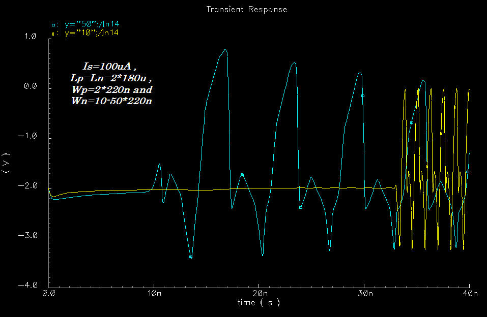
I try to change diff. MOS sizes , and I got the following oscillation result but only for Wp=2*220n ?
the output result shows some oscillation signal but its not clear as pulse shape?
even with change of Wn , the freq. is reduced isit due cpacitance of NMOS?
could u explain more please?
thanks
Hi ,,,
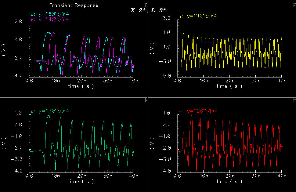
thanks for help, we get the following signal out of the ring , but as u see the output signal not squar pulsed signal like CMOS Inv ring? and if we increase the Wn the oscil. freq. get down . also it's oscil. in -ve ampl. ?
could u help by more explination?
thankx
output of the ring
You're using ideal current source which allows the voltage to go negative. When the NMOS turns on with a large delta-v, then it turns into a resistor by going into the triode-region. The voltage therefore on Voff/Vot goes lwo until either the resistance of the PMOS times the current equals the voltage, ot you move the PMOS into saturation and it becomes a current source. This probably explains also why you will not get a square wave, because the votlage swing is so large.
I suggest you either use a mos mirror on the bottom, or you put a diode clamp. This can be implemeneted by putting a "switch" from the analogLib library, and connecting the positive nodes to GND, and the negative nodes to the top of the current source. This should help the oscillation look square.
After you do that and your waveform still doesn't look quite as square as you like it, then it means its a slew rate problem still. For that you need to still tweak your NMOS size/ PMOS size and current for optimal slew rate/gain.
Hi ,,,
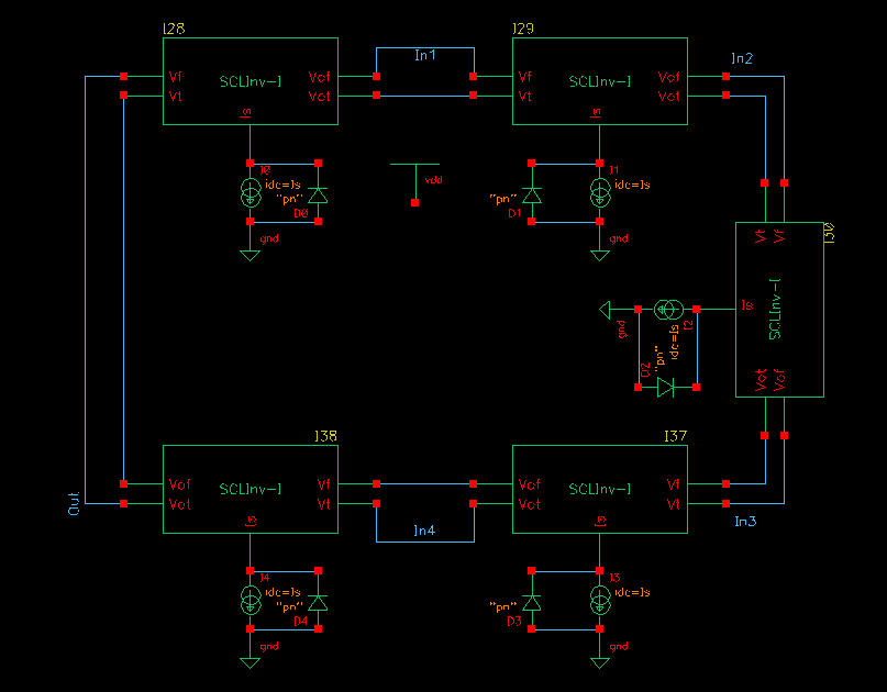
thanks for every body , well I try the second solution of "gszczesz" by adding clamping diode || to current source as he said but still the output as the prevous fig. . I will try to use CM as current source?
thanks
Added after 2 hours 2 minutes:
Hi
i have one remark , when i extend the transit analysis time e.g 20n i didnot get the oscillation where as if i leave to 10n , it's ok , i get the oscillation? is there any relation?
thanks
Please post how you connected the diode... It's not possible to get an average negative voltage without something that allows the average voltage to go negative. I suspect the diode is not working properly. In particular show the voltage on the current source which should never go below ground.
As far as the 10nS vs 20nS time, I'm not sure what is going on. How are you kicking the oscillator on? Normally you need to kick it into oscillation by either adding a switch that temporarily shorts one of the inputs, by kicking the supply, etc...
As we charactrize the SCL ring, the effect of Wn on frequency by mean of reducing it as it's increase. So , is the gm,n is effecting also. Is Wn effecting the freq. of oscillation due of changing the Av, then at cretin vlaue the ring will not oscillate because it's not satsfying the oscillation condition of loop gain >2???
thankx
This site uses cookies to help personalise content, tailor your experience and to keep you logged in if you register.
By continuing to use this site, you are consenting to our use of cookies.