shaikss
Full Member level 4
HI,
I am not fully aware of load modulation.
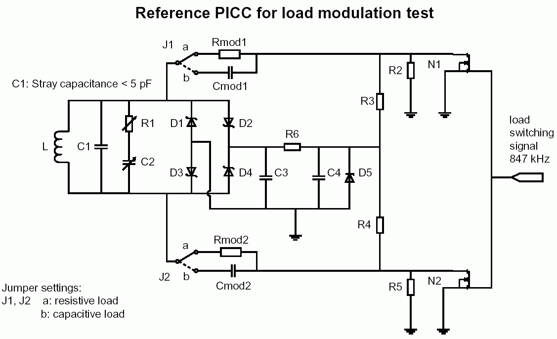
The concept I know about load modulation is : Passive RFID tags communicates and transfers data to the reader by means of load modulation in the LF and HF range. Because of inductive coupling, magnetic field induces a small current in the tag. Since, the reader and tag are inductively coupled, change in the load at the tag results in amplitude variations at the reader (due to voltage drop at the reader). This sounds OK. But what I am unable to understand is how to change the load ? The same applies to backscatter modulation too. In back scatter modulation which is used at UHF and microwave range, the incident energy at the tag is reflected back to the reader. Here, when you switch the transistor (load) connected to the tag antenna, data is transferred from tag to reader.
I don't understand the concept of how to change/switch the load or detune the resonant circuit. Please help me to understand the concept.
Thanks,
shaikss.
I am not fully aware of load modulation.
The concept I know about load modulation is : Passive RFID tags communicates and transfers data to the reader by means of load modulation in the LF and HF range. Because of inductive coupling, magnetic field induces a small current in the tag. Since, the reader and tag are inductively coupled, change in the load at the tag results in amplitude variations at the reader (due to voltage drop at the reader). This sounds OK. But what I am unable to understand is how to change the load ? The same applies to backscatter modulation too. In back scatter modulation which is used at UHF and microwave range, the incident energy at the tag is reflected back to the reader. Here, when you switch the transistor (load) connected to the tag antenna, data is transferred from tag to reader.
I don't understand the concept of how to change/switch the load or detune the resonant circuit. Please help me to understand the concept.
Thanks,
shaikss.