Continue to Site

Welcome to EDAboard.com

Welcome to our site! EDAboard.com is an international Electronics Discussion Forum focused on EDA software, circuits, schematics, books, theory, papers, asic, pld, 8051, DSP, Network, RF, Analog Design, PCB, Service Manuals... and a whole lot more! To participate you need to register. Registration is free. Click here to register now.

RFID reader and tag design

Status
Not open for further replies.

ArjunSC

Member level 1
Joined
Dec 24, 2005
Messages
39
Helped
2
Reputation
4
Reaction score
0
Trophy points
1,286
Activity points
1,669
Hi all,

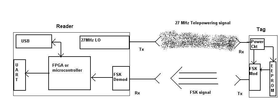
I am working on a RFID project. The requirement is to send a "27MHz" telepowering signal from the READER to the TAG, this is just a carrier wave to power up the tag and contains no data. Backscattering technique cannot be used here since the data that is sent back from the TAG should be at a frequency of 3.951MHz for logic'0' and 4.516MHz for logic'1' i.e: FSK technique is to be used rather than the conventional ASK. This requires two seperate antennas for both READER and TAG. The Tx antenna from the TAG and Rx antanna of the READER are centre tuned to a frequency of 4.234Mhz (This i hope everone can make out how).

The Design of both the reader and the tag is to be done for this setup. The mechanical size of the tag is not a big consideration.

Can anyone please guide me in this regard?
 

"RFID Reader and Tag Design"

You should state little bit more detail :
- What is the comm data rate
- Is tag to be passive or active
- Is it possible to build it on discretes
- What is the accepted tag sizes.
- What max distance you need for tag communication
- How stable the backscattering frequencies must be
- ( missed)

Solution proposal will greatly be affected by conditions above .
 

Re: "RFID Reader and Tag Design"

Hi Artem,

Thank u for the reply.

1)The communication data rate goes like this:

* A logic '0' corresponds to 7 periods of 3.951MHz.
* A logic '1' corresponds to 8 periods of 4.516MHz.

So the communication data rate is: 3.951MHz÷7 = 4.516÷8 = 565 Kbits Per Second

2)The tag is completely passive and the 27.095MHz carrier (tele-powering) signal sent by the reader has to provide power for all the components in the tag.

3)Yes Definetely discretes can be used.

4)The tag is placed on the railway tracks, so you can roughly estimate the maximum size(Lenghth, Breadth and Width). No particular standard decided yet.

5)The Reader antenna is placed at the base of the engine wagon and hence i estimate the maximum distance for communication would be a max of 10 feet.

6)There is no backscattering technique here since the Transmitting and Receiving antennas are different for both tag and reader. The Reader's Tx and tag's Rx are tuned to 27.095MHz and Tag's Tx and reader's Rx tuned to 4.234Mhz.

7) The mode of communication from the Tag to the reader is FSK.


The immediate problem is i am not getting a FSK modulator and demodulator circuit for this specification in the form of an IC or a circuit.

91_1156761359.JPG
 

"RFID Reader and Tag Design"

How stable the carrier frequency of FSK must be and what is the minimum response time after 27 MHz has been applied ?

Added after 4 minutes:

You can simplify via :

Calculate the reader Tx frequency to be closed to 27 MHz which mustbe multiple of 3.951MHz÷7 = 4.516÷8 = 565 KHz.
At receive side use precaler with variable division factor, supply it with reader TX frequency , then modulate signal by varying prescaler division.
Same technique used in modern tags to extract internal synch clock source .
 

    ArjunSC

    Points: 2
    Helpful Answer Positive Rating
Re: "RFID Reader and Tag Design"

ours company have a antenna of the tag and reader , it is dual frequency , 27.095MHz and 4.234MHz . at the same time , we have provided the tag to ours customer .

www. antlab. com. cn

we from Beijing .
 

Re: "RFID Reader and Tag Design"

Hi Mr Jim Liu,

Can we discuss about the design in this board, because we are also about to design a 27 MHz RFID concept.

If you are a technical person, can u pls help me with the FSK demodulator circuit for centre frequency of 4.2MHz.

Right now it is kind of urgent !!!
 

Re: "RFID Reader and Tag Design"

Hi all,

I am designing a FSK Demodulator circuit for my above described project. I am thinking of different techniques as described in some patent papers.

** one technique is to use ZCDs to convert the received wave into square pulses and then use a centre tuned oscillator in one path and give to D input of D f/f (fig below). the other path would be connected to clock input. The module works on the basis of phase lag and phase lead based on the input freq.

This is a simple technique and has some disadvantages like " the q factor of the oscillator shd be very high.

Can anybody pls reply with possible disadvantages of this design when used practically.

65_1157096127.JPG
 

Re: "RFID Reader and Tag Design"

Hi Arjan,

there is an IEEE paper on "digital communication for railway systems" you can get it in the forum by request, this paper might solve your problems .......
 

Re: "RFID Reader and Tag Design"

Do check RFID Handbook and its website. Its very good resource for the RFID design.
 

Hi all, lets continue this topic to know more about RFIDs .........

Lets talk about passive tags here ........... how can we use a sine wave signal to power up the passive tag .............. can anyone please discuss about the power electronics part of it ..................
 

Status
Not open for further replies.

Part and Inventory Search

Welcome to EDABoard.com

Sponsor

Back
Top