Continue to Site

Welcome to EDAboard.com

Welcome to our site! EDAboard.com is an international Electronics Discussion Forum focused on EDA software, circuits, schematics, books, theory, papers, asic, pld, 8051, DSP, Network, RF, Analog Design, PCB, Service Manuals... and a whole lot more! To participate you need to register. Registration is free. Click here to register now.

[SOLVED] RF transmitter and receiver circuit

Status
Not open for further replies.

doucheful80

Junior Member level 1
Joined
Dec 14, 2011
Messages
15
Helped
0
Reputation
0
Reaction score
0
Trophy points
1,281
Activity points
1,414
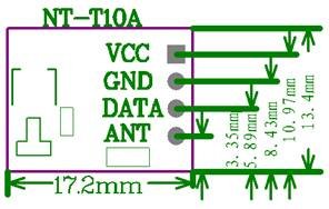
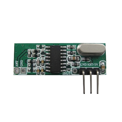
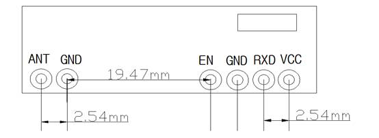
I ve purchase a NT-T10A (433 Mhz trasmitter) and CWC-12 (433 receiver), but i cant get them to work just by simply connecting 5v, tx ,rx and ground to their pin. Does anyone here know a link to view a good circuit for it?

There is also a ANT pin on the receiver without an anthena (there is a soft wire coil on transmitter), should i solder on one by myself..if yes can i use normal wire?
 

83_1323926143.jpg


http://www.nice-tech.cn/en/productshow.asp?id=182
https://www.edaboard.com/threads/202751/

1.Universal rf transmitter
2.No encoder
3. 200m range in open area
4. 3V lowest power

Specifications for the rf transmitter:
Working voltage: 5V∼12V
Working current: 40mA (at 12V), 9mA(at 5V)
Resonance mode: sound wave resonance (SAW)
Modulation mode: ASK /OOK
Working frequency: 315MHz-433.92MHz, customized frequency is available.
Transmission power: 25mW (315MHz at 12V)
Frequency bandwidth: + 150kHz (max)
Velocity: ≤10Kbps
Aerial Length: 24cm (315MHz), 18cm(433.92MHz)
a. The aerial is employing soft lead wire or other hard metal (like telescopic aerial), the length should be chosen according to the respective frequency (see some technical documents of our company). If the aerial is using soft lead wire, it should be stretched as straight as possible in using.
b. If applying the module inside the module housing, the antenna should be fetched out of housing. To connect the metal telescope aerial with 50ohm coaxial line will get better effect in transmission.
 
Yes ive seen all of the sites given..the links does not provide application note to the specific model im using, just rating only
..the aerial is refering to transmitter..the receiver does not come with an anthenna so im not sure about receiver side..should i solder an anthenna to it or not

---------- Post added at 14:31 ---------- Previous post was at 14:27 ----------

if i connected the circuit correctly..what shud i see on the anthenna when i connect it to an oscilopscope..so far i used 5v and there is not output
 

Aerial length depends on frequency either receiver or transmitter. They could be quarter wave. For receiver longer length may be used. It does not matter for short ranges (it will work without aerial). Provide +V to data pin (for testing). As there is no built in encoder. PT2262 and PT2272 are ready made encoder and decoder. See their datasheet for their implementation in RF link.
See the signal at receiver end. Without transmitter signal, there will be loud noise in audio range(hissing sound) ar Rx pin.When transmitter signal is present, noise will disappear indicating link is established. At transmitter end, you may observe envelope of RF power, although difficult with scope. Connect ground of scope with transmitter.

**broken link removed**
42_1323934184.jpg

45_1323936042.jpg

Technical parameter
Working Voltage: DC 5V
Working Frequency: 315,433.92 MHz
Working current: 2.2 mA
Sensitivity: -106dBm
Working Temperature: -20 ℃ ~ +70 ℃
Size: 36 × 13 × 5mm
Products
Low power consumption, 5V supply, 433.92M current of 4mA , 315M current of 2.2 mA ;
High sensitivity, the internal use of phase-locked loop frequency stabilization, the receiving frequency stability;
Different rates according to different needs can choose the best remote distance;
Product consistency, cost-effective.

Pin Description:
Pin
Name
Function
1
ANT
Antenna connection
2 , 4
GND
Negative power supply
3
EN
Enable (active low)
5
RXD
Data output
6
VCC
Positive power supply

Overall dimensions (mm):

Applications
Applications: wireless remote control, remote control toys, burglar alarms, garage doors, rolling gates, automatic barrier, retractable doors gated industry.
Optional accessories

Emission line with the company, supporting the use of remote control products.
Remarks
VCC voltage is consistent with the module operating voltage, and power to do the filtering;
Reception antenna module a great impact, then the best 1 / 4 wavelength antenna, generally 50 ohm single-core wire, the length of the antenna is about 315M of 23cm, 433M of about 17cm;
Antenna position also affects the reception of the module, install the antenna as straight, away from the shield, high pressure, and where the source of interference ;
Frequency used to receive, decode mode and vibration resistance should match with the launch.
This module is adjustable demodulation bandwidth, demodulation bandwidth of conventional factory 2.5K .

Receiver has an enable pin. Connect it with ground to make receiver active.
What is the remote controlled device, you are making?
 
Last edited:
HAHA thx..its funny that i just receive this link from the shop owner before u replied..
anyway will try to solder the ground and enable pin tomorrow and place it to ground tmr..
did u realize that the enable pin is label SHUT instead of EN in the picture..mine is also exactly the same..how would i know i need to place it to low..

Im building an ultrasonic positioning system..firstly the distance between the ultrasonic trasmitter and receiver needed to be found out. Which this two are separate..and i need to sync the time where the trasmitter start transmitting and the start of the timer that measure this delay. I tried three methods so far..fail the first two

1. Use a tx/rx on both side..so that it will go like A(transmit), B(receive), B(transmit after receive), A (receive ), then i just divide the time by half..but the problem was although i prevent it from receiving it own signal in A, without ON B, there is still a distance..which i duno why
2.Second way is that there is an sync pin..where B only start the transmit after receive a signal from A. The problem here was the interrupt on PICF4520..the interrupt seems to not branch in the pic...but in simulation it does (MPLAB SIM). I check all the datasheet..everthing..my lecturer advice me to try real time simulating (the interrupt is important in restarting the process immediately and ensuring accuracy
3. is to use RF, which sync it as RF travel by speed of light..so we can assume that both start virtually the same time : ) thanks by the way
3
 

As shut(Enable) pin in not present physically, it already may be connected to ground .
Did you take into account processing time including modulation and demodulation timing. And signal echoing.
If the object is in line, a light beam can also initiate.
 
Last edited:
nope i did not do any modulating..its not echo..the same distance keep display even after i change position..possibly effected by previous cycle..but i cant figure out wads wrong still..so gave it up
nope its not in straight line
i just tested SHUT with ground (using multimeter) its not connected..so nid to solder it
thank for ur help anyway
 

Hi alertlinks..yes you are correct..i connected the enable pin to ground and it work just like u said..the rx pin is noisy when the tx pin is not high...when high, the rx pin goes low..but only for a short while..so im guessing i need to used a PIC program to measure the low time and generate an output upon detection..thank you anyway,been much help :)
 

Status
Not open for further replies.

Similar threads

Part and Inventory Search

Welcome to EDABoard.com

Sponsor

Back
Top