Continue to Site

Welcome to EDAboard.com

Welcome to our site! EDAboard.com is an international Electronics Discussion Forum focused on EDA software, circuits, schematics, books, theory, papers, asic, pld, 8051, DSP, Network, RF, Analog Design, PCB, Service Manuals... and a whole lot more! To participate you need to register. Registration is free. Click here to register now.

rf to dc converter schematic needed

Status
Not open for further replies.
More harmonics are better! the whole purpose of the device is to produce as many of them as possible. If you insert the filter all you will do is halve the DC bias available so you may then have to resort to a voltage quadrupler to get back where you started!

I doubt a 1N23 will work any better and it may be significantly worse. The property you need in the diode isn't it's microwave performance but it's rapid switching action. The harmonics are generated by the rapid turn-on and turn-off as it moves to and from conduction, that's why fast and step recovery diodes work best.

Brian.

Hello,
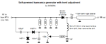
here is the final schematic.
You were right about the filter, it reduces too much the bias voltage and I have not noticed a significant improvement in "unwanted" harmonics generation. The voltage doubler produces about 36v loaded by the diode, which is brought up to 0v with the potentiometer. The harmonics attenuation is great under this range, the full screen in my analogue spectrum analyzer. The harmonics and level depend also on the input frequency, as well as the input level, as these affect not only the harmonics diode but also the doubler response. I have not made any serious measurements yet, but overal very satisfied by such a simple circuit, a great way to produce test signals for the uhf/microwave, if efficiency does not matter.

I wonder, if I use a single diode passive mixer and connect it to the harmonics generator, will the mixer be able to shift up generated frequencies even more...it should?
 

Attachments

  • myharmgen.png
    myharmgen.png
    16.4 KB · Views: 59

It should work but remember the circuit needs quite a lot of Tx power to operate well. This kind of 'comb' generator is used in some HF receivers to generate the local oscillator. They start with say 1MHz and pick off 2MHz, 3MHz and so on using a tunable filter. The output is then mixed with an oscillator tuning the 1MHz between harmonics. It results in lots of 1MHz wide bands without having to use wide range VCOs. The downside is they have horrible rejection of frequencies 1MHz away due to leakage through the comb filter.

I'm glad you mention removing the drill from the coil. I had visions of keying the transmitter and it flying out and cutting a hole through the wall :smile:

Brian.
 
  • Like
Reactions: neazoi

    neazoi

    Points: 2
    Helpful Answer Positive Rating
Thanks Brian
I mention to remove the drill because the inductance will be much different with it in place. This may not be obvious for someone not experienced with rf. A while ago I was confused with a similar coil, not using a drill core of course.
Hey, we are making a coilgun gere! :D
 

More harmonics are better! the whole purpose of the device is to produce as many of them as possible. If you insert the filter all you will do is halve the DC bias available so you may then have to resort to a voltage quadrupler to get back where you started!

I doubt a 1N23 will work any better and it may be significantly worse. The property you need in the diode isn't it's microwave performance but it's rapid switching action. The harmonics are generated by the rapid turn-on and turn-off as it moves to and from conduction, that's why fast and step recovery diodes work best.

Brian.

I am so far not sure from all above what you are trying to do.
I started with "rectifying RF of about 1W" without telling the frequency. I explained what best to do.

Next you started wishing your voltage doubler to double the frequency, now using 1N23 at 144 or 432 MHz. All this is nonsense. 1N23 is an X-band Si mixer diode which will get killed with 50 mW. Biasing a diode detector at 1W input is again a nonsense.
You can build a varactor frequency multiplier with 1W input at144 or 432 MHz, but as I have designed many similar devices, you will need a lot of experience and special varactor diodes to succeed.
So what you really want?
 

I am so far not sure from all above what you are trying to do.
I started with "rectifying RF of about 1W" without telling the frequency. I explained what is best to do.

Next you started wishing your voltage doubler to double the frequency, now using 1N23 at 144 or 432 MHz. All this is nonsense. 1N23 is an X-band Si mixer diode which will get killed with 50 mW. Biasing a diode detector at 1W input is again a nonsense.
You can build a varactor frequency multiplier with 1W input at 144 or 432 MHz, but as I have designed many similar devices, you will need a lot of experience and special varactor diodes to succeed.
So what do you really want?

I agree with all that.
Neazoi, you really are not being very specific in what you are trying to achieve.
I too have used varactor multipliers (triplers) from 144 to 423MHz and also 432MHz to 1296MHz, these are very successful and relatively easy to build and get operating. On this page of mine ( ~ half way down) there is a varactor tripler from 432 to 1296 internal photo and circuit diagram. It requires NO EXTERNAL POWER SUPPLY. The varactor diode is the old favourite BAY96 and can handle up to ~ 15W input. Its ~ 40% efficient

Dave
 

In defence of Neazoi, he started with someone elses internet article describing a low power multiplier using a signal diode. The diode was reverse biased and brought to conduction by peaks in the RF drive signal in an attempt to optimize the harmonic content. It was more of an experiment to see what could be done to produce low level, wide spectrum harmonics at low cost than to make an efficient high power multiplier. It was pointed out that a 1N23 was not suitable and a purpose designed device would work better.

Brian.
 
  • Like
Reactions: neazoi

    neazoi

    Points: 2
    Helpful Answer Positive Rating
Exactly Brian, thank you
If you follow the whole conversation, you should be able to understand this.
Sorry about my English though.
Sometimes, you begin with a though and then the conversation leads to another outcome etc..
 

Status
Not open for further replies.

Similar threads

Part and Inventory Search

Welcome to EDABoard.com

Sponsor

Back
Top