Continue to Site

Welcome to EDAboard.com

Welcome to our site! EDAboard.com is an international Electronics Discussion Forum focused on EDA software, circuits, schematics, books, theory, papers, asic, pld, 8051, DSP, Network, RF, Analog Design, PCB, Service Manuals... and a whole lot more! To participate you need to register. Registration is free. Click here to register now.

RF system design Ku,X and C band

Status
Not open for further replies.

andrishev

Member level 1
Joined
Mar 5, 2006
Messages
33
Helped
1
Reputation
2
Reaction score
0
Trophy points
1,286
Activity points
1,511
satcom uav mbps loss caculation

I wanna know if i can design an rf communication system at Ku band 12 to 14GHz
what will be the specification of my receiver transmitter.
How can i make a link budget analysis
what topologies i must use?
are spectrum analyser,network anlayser and signal generator enough for testing such a design
Can i use @ds for such a dsign?
i am a new rf engineer and i wanna design such a system but first i must gain experience
Can you help?
I have many questions and not clear about designing such systems.
:!::!::?::idea::idea::idea

Added after 2 minutes:

Also
data rate 45Mbps/10 MBps
distance >LOS< 200km
ground antenna directional
Unmanned air vechile antenna directional
Spread spectrum
 

200 km rf antenna

1. Start with finding good channel models. You will not have problems with multipath but channel loss will severely depend on the weather (clowds, pollution, rain, ...)
2. Once you know the worst-case link loss, with the maximum transmit power (which is defined by the technology; typically 10 dBm at 12 Ghz I assume), you know the power that arrives at the receiver.
3. If you know your bandwidth, you also know the noise. Spread spectrum leads to processing gain. This defines you receiver sensitivity.
4. If the required sensitivity is higher than the signal you receive in worst case, you will need directional antenna to improve the gain. Sattelite dishes e.g. have gains starting from 30 db!

I think this is a start for your RF system design.

Added after 1 minutes:

What technology do you think you will work in? Discrete or integrated circuit?
 

    andrishev

    Points: 2
    Helpful Answer Positive Rating
usat satellite link budget calculator

Thank you for your reply

I will work with integrated circuit

bandtwidh will be 200MHz so N=KTB=1.38*10e-23*290*200e10e6=-120dB
am i correct?
Also i found a power amplifier that is 25W which is 13dBW so i think i can get more power from my transmitter

Also i made a link budget analysis with BER 10e-6;D=200km;Ku band(13GHz);Both antennas are directional but the gain of airborne antenna is limiited
to 15db because of size limitations;data rate 45MBps;PCM

But i found an enormous power need for transmitter output (antenna gain included) 101dBm ;(antenna 35-45dB assumption)which means i need a power output of 10e3W

where can i find information about link budget analsis.

Also i am lookink for satellite systems but now i am only investigating.

Do you know tools for link budget analyses for such systems

<thank you very much for your helps<

Added after 1 hours 23 minutes:

MPC8-1520 series 125W pulsed Ku-band power amplifier, 12.75GHz to 18.0GHz outdoor solid state power amplifier.
also there are amplifiers with much output power

Added after 3 hours 45 minutes:

transmitter 8 watt ;1dB compression point 42dBm
and SSPA (power amplifier) 20W:1dB compression point 43 dBm

what will be my Tx power in link budget analyses
will it be 42dBm
or 42+43dBm
 

c band data link

For a 200 MHz BW, kTB Thermal noise is -120 dBW, or -90 dBm (You need to make sure that you keep the units right)

If you are trying to track a UAV, you will need to either
1-have a tracking antenna, which would be troublesome
2-Use an omni-directional antenna, which will be trouble for the antenna gain.

I don't think you will be able to get 45 MBs over 200 km very easily, that's pretty difficult.

Dave
 

    andrishev

    Points: 2
    Helpful Answer Positive Rating
uav airborne ku band antenna

bandtwidh will be 200MHz so N=KTB=1.38*10e-23*290*200e10e6=-120dB
am i correct?

I agree with RFDave:
-174+6 (noise figure) +10log(2e8)=-87 dbm

Also i made a link budget analysis with BER 10e-6;D=200km;Ku band(13GHz);Both antennas are directional but the gain of airborne antenna is limiited
to 15db because of size limitations;

It still seems strange to me, having an UAV at 200 km distance is far - very far. I assume you will have to reduce the spec. At
https://www.satsig.net/satellite-tv-budget.htm
you find a link budget calculation for satellite, at 12.75 GHz. This predicts 200 dB channel loss, for a distance of merely 40 km!

data rate 45MBps;PCM
What do you need that bandwidth for? HDTV? Even DVB-T needs only 6-7 Mbps.

MPC8-1520 series 125W pulsed Ku-band power amplifier, 12.75GHz to 18.0GHz outdoor solid state power amplifier.
Nah this is a pulsed amplifier used for radar which needs to transmit very short but powerful RF pulses. Not useful for your app.

transmitter 8 watt ;1dB compression point 42dBm
and SSPA (power amplifier) 20W:1dB compression point 43 dBm

This seems a more reasonable alternative, but have you checked the physical size of such an amplifier? Can this be carried by your UAV?
 

    andrishev

    Points: 2
    Helpful Answer Positive Rating
satellite link budget c band for 4 mbps video

I need this bandwidth because i take real time EO/IR payload (video data), SAR(syntetic aperture radar data, noise camera data and telemetry from airborn
maybe i can't achieve this rate but i need high data rates.

i will use 200MHz bandwith because i also code my data with spread spectrum or another techniques so i need more bandtwidth.My link will be full dublex. Uplink 200Kbps(more important because i don't wanna lose my airborne with a data link error) Downlink 10.71 and 45Mbps.

My airborne is big enough to carry theese amplifiers and transmitters it will weight >3000kg Also i will have SATCOM in my airborne i need 2Mbps data rate for my SATCOM link. The problem is to mount the SATCOM airborne Antenna to my Airborne.

Also i will use a tracking directional antenna with a diameter aproximatelly 1.2meter with ~34db gain.

I think i don't have fresnel zone problem with my data link(what do you think?)

Added after 2 minutes:

Also i wanna talk about another transmitter receiver system at 436MHz with a distance 30 km What data rate i can achieve and What problems will i have with this link.

are the structures of transmitters with these frequencies(436MHz) and Ku band frequencies same
i mean Topologies and the circuits PLL,VCO and TCXO combination for LO for example.

Added after 30 minutes:

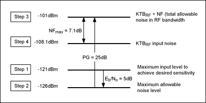
KTBRF(log) = 10 log(1.381 10-23 W/Hz/K * 290K 200MHz * 1000mW/W)
=-90dB

yes you are right i forget 1000mW

Added after 8 minutes:

-174+6 (noise figure) +10log(2e8)=-87 dbm
i think noise figure is not included with KTB

example:
40_1160831548.gif
 

rf receiver design in c band

Sounds like an interesting program. Is there a web page that describes the whole thing?


Dave
 

    andrishev

    Points: 2
    Helpful Answer Positive Rating
    V

    Points: 2
    Helpful Answer Positive Rating
c band transmitter design

you can find completed projects by searching UAV concept in google.
Also predator,globalhawk are some favorite UAVs
UAV concept is a developing and new concept
 

    V

    Points: 2
    Helpful Answer Positive Rating
Status
Not open for further replies.

Part and Inventory Search

Welcome to EDABoard.com

Sponsor

Back
Top