Continue to Site

Welcome to EDAboard.com

Welcome to our site! EDAboard.com is an international Electronics Discussion Forum focused on EDA software, circuits, schematics, books, theory, papers, asic, pld, 8051, DSP, Network, RF, Analog Design, PCB, Service Manuals... and a whole lot more! To participate you need to register. Registration is free. Click here to register now.

RF Remote TX/RX issue - need a little help understanding

Status
Not open for further replies.

officework13

Newbie level 5
Joined
Mar 6, 2012
Messages
9
Helped
0
Reputation
0
Reaction score
0
Trophy points
1,281
Activity points
1,442
i am trying to help a local club with a wireless custom application that i can possibly do for about $300 and my time for free, vs the vendor purchased product for about $2000.
i am looking at doing a project using already built components of a rf transmitter and receiver (ASK, OOk and 433Mhz, and i believe it is SAW). i will be transmitting a signal to 8 receivers which are on a relay to momentarily turn on the motor.
i need the ability of all 8 channels to transmitt signal simultaneously. - i also need the ability to wire the transmitter to the source.
i need an 8 channel transmitter (can be either 1 8 channel, 2-4channel or 8-single channel transmitters)

so i need to know, will an 8 channel transmitter work like this or will it need 8 single channel transmitters.

if i go with 8 single transmitters (the one i am looking at) it does not have an encoder/decoder. does this make it less secure. or do you only need the encoder/decoder when you are transmitting/receiving for more than 1 channel.

thanks
 

I fear, all the "multiple channels simultaneously" stuff is completely meaningless if you don't talk about the kind of transmitted information and data rates.
 

sorry about that. it is b/c i do not exactly know/understand the terminology for that part. here are the specs of the transmitter.
Operating Voltage:DC 9 V
Operating Current:More than 100mA
Quiescent Current:Less than 20uA
Transfer Rate:2.4Kbps(Max.9.6Kbps)
the transmitted information/data would be similar to unlocking the door/trunk of a car. push the button and the door unlocks. mine will be the same exept it works as follows.
i have a special computer controller that has 8 buttons and is hooked up to 8 relays (each going to a separate motor). if button 1 is pushed relay 1 closes the circuit allowing the current to pass through (i believe it is 12volt but very low amps). there are 2 wires attached to this relay which are 100 meters long and go to the other housing which i believe is hooked up to another relay which is tripped and allows the motor to run until an arm comes around and hits the microswitch and turns off the motor. (in some cases i may only press 1 button while in other cases i will press all 8 buttons at the same time). my intent is to eliminate the 100 foot extension cords. to each of the 8 machines.
thanks for you willingness to asssist.
 

I understand that here in this situation involving one transmitter and 8 receivers using the 433MHz frequency band. This is not difficult to achieve, can be used for example HOLTEK HT12E/HT12D encoder/decoder series.
Still remains to specify how many separate commands must be transmitted to the receivers (except for the start common control) and if these commands have to be decoded by all receivers involved or not.
 

from what i understand, there is only 1 command for the momementary switch and that is to turn on. what i think becomes a bit more complex may be that there are various combinations of buttons 1 to 8 being pressed. for simplicity, pressing 1 encodes to signal 1 and is received by receiver 1 where it is decoded and triggers the relay.
pressing 2 encodes to signal 2 and is received by receiver 2 where it is decoded and triggers the relay
pressing 1+2 at the same time is now encoded to a new independent signal and must be decoded by each individual receiver. (with only using these 2 combination i would need to program the receiver to understand these signal combinations)
therefore, for each possible button combination (which for 1 there is 1, 2 there are 3, 3 there are 7, 4 there are 16 (i think), which means by the time i get to 8 there are lots) i would need the applicable signal recognized by each individual receiver to understand that it is to trip the relay. this seems very complex if such is the case as i would be sitting with each receiver for hours to program it for all the combinations.
that is why i am thinking that if i went with 8 single channel transmitters, it would not matter if 1 or 2 or 3 or 8 buttons were pressed, as each signal is always independent and therefore each receiver would only have to understand 1 signal.
is this somewhat clear and am i correct in my logic.
 

If you use an HT12E encoder /HT12D decoder there's a possibility to transmit and decode four simultaneous commands to four receivers, each receiver by allocating it by one of the 4 decoded outputs.
So, in theory one solution (in order to use 8 channels simultaneously) would be to use two sets of transmitters, each tuned to another frequency and transmitting signals to a group of 4 receivers ...

---------- Post added at 02:14 ---------- Previous post was at 02:01 ----------

I have found similar 8 bit encoder/decoder circuit:
https://www.northriverrailway.net/PDF/CIP-8.pdf
Using this you may do the trick…

---------- Post added at 02:19 ---------- Previous post was at 02:14 ----------

also see the CTA88 series:

https://www.radiometrix.com/files/additional/cta88_demo.pdf
 

you need to transmit to all 8 possibly at the same time. Since 8 transmitters at the same frequency will jam each other, you can do it one of two ways:

8 transmit receive pairs spaced at 8 different frequencies
1 transmit and on receiver with a digital packet of bits. The bits tell which function to turn on or off. You could do 1 tranmitter and 8 receivers too, but with the same long packet.

A microcontroller is the easiest way to decipher the packet information.
 

thanks guys for your help.
Biff44, my testing this morning informed me that i can not use 2 tranmitters at the same time on the same frequency.
also, i now understand what you mean by using the 8 different frequencies mathced with 8 diff receivers. i was not thinking of doing that as then if i wanted a spare receiver i would have to have 8 separate ones instead of just 1. (same goes for transmitters).
i am interested a bit more in your comment on how to do this wth the 1 transmitter and 8 receivers, but i think if i am correct that this would require a microcontroller and then this may be (no is) getting into more than i have skills for. see below a bit more info what i have.
i am being educated in RF, beyond what i was hoping to do. every time there is a new post to my question, i think i end up reading another 20 pages to understand the terminology. Now that i am this far in my learning i think the solution is around the corner and hate to give up now. so here is a bit more and perhaps this wil assist in what you an provide me.
the supplier i was looking to get the transmitter and receiver from is
https://www.rfremotech.com/TransimittingModules.html
the transmitter is the TM1000-4 and it uses a PT2262 encoder.
the receiver module is a RR1LNC and i am not sure what the decoder is but do not think it is the PT2272 as i can not see at part on the receiver and also it is a learning code receiver.
**broken link removed**
the vendor says i could use the 4 channel transmitter for the 8 receivers as follows.

TM1000-4 is Fixed code and comes with 8 encoding pins. For controlling the 8 receivers as your requirement, you can use 4 of the encoding pins.
Data Pin 10 for Rx1
Data Pin 11 for Rx2
Data Pin 12 for Rx3
Data Pin 13 for Rx4
Data Pin 10 & Encode Pin 1 for Rx5
Data Pin 11 & Encode Pin 1 for Rx6
Data Pin 12 & Encode Pin 1 for Rx7
Data Pin 13& Encode Pin 1 for Rx8
Also, use the pins combinations for your application for activating different receivers at the same time.

Does this make any sense to you, i am afraid this is more than i can handle. i thought there would be an easy way to this project, but guess that is not happening.
But if nothing else i have become more educated in RF.
using simple terms for what he is suggesting above, what would i have to do to both the transmitter and each of the receivers.
if this is beyond what this forum is here to provide please let me know as i will not be offended.

i am not dead set on using this vendor, and so if there is a relatively inexpensive method to do what i am trying to achieve, requiring little to no modifications, i would be interested in other options.
thanks again.
 

Need to pay attention to the circuits I have introduced in post #6. (CIP-8 , CTA88)
That’s just an example of 8 independent channels encoder/decoder ready to be used in your particular application. Problems solved using this circuit, see the datasheet here
https://www.northriverrailway.net/PDF/CIP-8.pdf
 

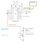
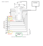
Attachments

  • TX module.png
    TX module.png
    79.7 KB · Views: 96
  • Receiver 1 diagram.png
    Receiver 1 diagram.png
    65.5 KB · Views: 83
thanks guys for your help.
my testing this morning informed me that i can not use 2 tranmitters at the same time on the same frequency.


Here is my shocked face!!!8-O

BTW, that is not entirely true. You CAN use 2 transmitters on the same frequency, but they can not be both on at the same time--i.e. you need time division multiplexing.


Have you tried posting on a hobbyist site, like this one?
https://forum.sparkfun.com/viewforum.php?f=13&
 
Last edited:

Thanks Mister_rf.
so after a few hours of reading and learning what certain electronic circuit symbols mean, i believe i understand how that works. so i will translate what i see in that diagram.
the button/s for the transmitter are pressed (does not matter if 1, 2, 3, 4...8 are all pressed at the same time) these then enter the encoder where they are encoded and then go out to the RF transmitter where the signal is transferred to all 8 receivers. now the receiver data out pin is hooded to the decoder data in pin where the data is decoded and based on the button/s pressed the receiver/s would transmitt a signal to close the circuit on the relay. example. button A (for Receiver A) is hooked to D0 and B (hooked to receiver B) to D1, and both were pressed, then a signal for D0+D1 would be encoded and sent by the transmitter, received by the receiver then decoded (by the decoder) and told to send a signal to D0 & D1 which would then close the relay on the Receiver A + B.
it is then my understanding that this then is an 8 channel transmitter (fixed code) and the receiver if hooked with 8 relays woudl be considered an 8 channel receiver. however, in my case since i would only be hooking 1 relay to each of the 8 data pins it would only be single channel receiver.

do i have the above understood corectly or am i way off.
additionally, when looking at the schematics
1. For each of the D0 to D7 on the Decoder what must these pins be connected to if i do not hook them up to a relay drive circut. or do i just leave them on their own.
2. for pin A0 it can get hooked to ground or Vcc (depending on baud rate desired) while pins A1 to A7, are hooked to the ground (as shown). and based on my knowledge this becomes only 1 of 256 possible combinations for this fixed code. However, could each of the pins A1 to A7 also be hooked to the Vcc (b/c it says it needs all pins to be hooked to Vcc or ground) and if so, is this where they can be connected to a dip switch to provide for the various addresses and the address set for the transmitter must match the address set for the receiver or it will not work. if my logic is true, then this would result in the ability to select one of the 256 unique addresses. am i correct in my understanding.

Biff - thanks, i like your facial comment. - i bet that gave away how much i understand in RF, but suprising after reading numerous posts that i was not the only one who did not know that. i am surprised that i did not come across such posting in may vast amount of readings. alos i checked out that web forum but i did not find any relevant info on RF. thanks though.

hows this for friday night fun.:???:
 

The sparkfun site is for you. Someone there probably already has code written to do what you want using standard available modules.
 

biff44
i will have a look at it again, but perhaps you can explain what you are referring to when you say written code. written to what? does that mean i would have to have some sort of controller (adurino) added to my RF module that can be programmed using a computer.
 

Consider to use the HT12E (Encorder)
**broken link removed**

and HT12D (Decoder)
**broken link removed**
 

@pico
No, you can’t use those encoders/decoders because are limited to only 4 bits of data as we have discussed earlier.

---------- Post added at 12:03 ---------- Previous post was at 11:06 ----------

...do i have the above understood corectly or am i way off.
Yes that’s correct.
additionally, when looking at the schematics
1. For each of the D0 to D7 on the Decoder what must these pins be connected to if i do not hook them up to a relay drive circut. or do i just leave them on their own.
Leave them unconnected. For each receiver use only one dedicated output to control the necessary relay.
2. for pin A0 it can get hooked to ground or Vcc (depending on baud rate desired) while pins A1 to A7, are hooked to the ground (as shown). and based on my knowledge this becomes only 1 of 256 possible combinations for this fixed code. However, could each of the pins A1 to A7 also be hooked to the Vcc (b/c it says it needs all pins to be hooked to Vcc or ground) and if so, is this where they can be connected to a dip switch to provide for the various addresses and the address set for the transmitter must match the address set for the receiver or it will not work. if my logic is true, then this would result in the ability to select one of the 256 unique addresses. am i correct in my understanding.

Yes, that’s true. The initial schematics use a fixed address, but this can be changed as you wish, in order not to interfere with other devices in that area.

---------- Post added at 12:10 ---------- Previous post was at 12:03 ----------

The sparkfun site is for you. Someone there probably already has code written to do what you want using standard available modules.
If we search the internet we may find various examples of microcontroller based encoding/decoding circuits, some examples here:
http://electronics-diy.com/schematics/185/codec.html
http://jap.hu/electronic/codec-v4.0.html

Also, if we have some time we can create our own systems see the Manchester Coding Basics example provided here:
http://www.atmel.com/Images/doc9164.pdf
 
Thanks mister_rf. for you comments and assistance and those links.
a few more clarity items/additional info.
on the diagram for the transmitter above, there is a transmit enable pushbutton (green box). my understanding is that this is what transmitts the signal. so in my case, if i had a momentary pushbutton for D0 to D7 would i then have to press each of the buttons i wanted transmitted along with pressing the TE button. if such is the case, how would i go about doing this so that i would not have to hold both the data button and TE button down at the same time but rather only have to press the data button (or would this not work).

additionally, if by chance when i pressed data button 1 and 2 but not exactly at the same time but say 1/2 second apart, would both corresponding receivers 1+2 still decode this to know that buttons 1+2 were pressed. would it matter if the delay when pressing the buttons was more or less than the 1/2 second apart.

or does the above only work when you use a toggle switch being either on/off for each of the data buttons and then if they are on then you press the TE button.

So now that i have most of this somewhat figured, do i have to build this all from scratch and test this on my own, or does a complete circuit board exist (i dont want to recreate the wheel if i do not have to), and if so where would be a good place to get it or track the materials down for what i need.

Also, on the transmitter diagram it shows D0 to D7 being hooked to SPDT switches (so it is either hooked to Ground or Vcc), for my application i have a computer controller that has the 8 relays (the relays are integrated into the circuit board and there are only 2 wires coming out from each relay) which would act as a SPST switch connecting the data (0-7) to the Vcc for each one. Therefore, how would i work this so that i could use this with the computer controller and SPST relay.
to complicate matters even further, i would like to use either the computer controller as well as manual control of the transmitter. my concern is that if the manual control pushbutton is a SPDT swithch that is not pressed has the D0 connected to Ground, and then when the computer controller trips relay/button 1 (hooked to D0) the it will complete the circuit for D0 and Vcc resulting in a short between Vcc and ground.
any ideas.

lastly, all of my machines are hooked to a 12v car battery and it appears that this encoder/decoder is on a 5v power source. i know i can get external 12to5 voltage converters or would it be better to just hook up 12v and put a LM7805 regulator on here (or will there be too much heat dissapation). using either of the methods will i have any issues if i have anywhere from 12-13.65 volts in the batteries.
thanks again.
 

on the diagram for the transmitter above, there is a transmit enable pushbutton (green box). my understanding is that this is what transmitts the signal. so in my case, if i had a momentary pushbutton for D0 to D7 would i then have to press each of the buttons i wanted transmitted along with pressing the TE button.

Yes, that’s correct.

if such is the case, how would i go about doing this so that i would not have to hold both the data button and TE button down at the same time but rather only have to press the data button (or would this not work).
In this situation that’s better to use some switches, not push buttons, each time the first step in this procedure to prepare the needed combination and second time to press the transmit button.
additionally, if by chance when i pressed data button 1 and 2 but not exactly at the same time but say 1/2 second apart, would both corresponding receivers 1+2 still decode this to know that buttons 1+2 were pressed. would it matter if the delay when pressing the buttons was more or less than the 1/2 second apart..
Need to have data prepared before transmit button pressed.

or does the above only work when you use a toggle switch being either on/off for each of the data buttons and then if they are on then you press the TE button.
Yes.

So now that i have most of this somewhat figured, do i have to build this all from scratch and test this on my own, or does a complete circuit board exist (i dont want to recreate the wheel if i do not have to), and if so where would be a good place to get it or track the materials down for what i need.
I don’t have any details about off the shelf products to be used in a similar application. :roll:
Also, on the transmitter diagram it shows D0 to D7 being hooked to SPDT switches (so it is either hooked to Ground or Vcc), for my application i have a computer controller that has the 8 relays (the relays are integrated into the circuit board and there are only 2 wires coming out from each relay) which would act as a SPST switch connecting the data (0-7) to the Vcc for each one. Therefore, how would i work this so that i could use this with the computer controller and SPST relay.
to complicate matters even further, i would like to use either the computer controller as well as manual control of the transmitter. my concern is that if the manual control pushbutton is a SPDT swithch that is not pressed has the D0 connected to Ground, and then when the computer controller trips relay/button 1 (hooked to D0) the it will complete the circuit for D0 and Vcc resulting in a short between Vcc and ground.
any ideas.
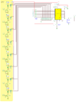
To avoid additional problems( between manual and automated control) we may insert to the GND on each section of the data switches some resistors. But as long there is no information about D0-D7 inputs current in the datasheet, we need to consider as the maximum resistor value must keep the low level voltage lower than V max= 0.2 Vcc = 1V, so in theory we can place 8* 1k ohms resistors to the GND, but in practice this theoretical value need to be tested. :-D
See the diagram attached.
lastly, all of my machines are hooked to a 12v car battery and it appears that this encoder/decoder is on a 5v power source. i know i can get external 12to5 voltage converters or would it be better to just hook up 12v and put a LM7805 regulator on here (or will there be too much heat dissipation). using either of the methods will i have any issues if i have anywhere from 12-13.65 volts in the batteries.
I assume this encoder and the decoder circuits has low power consumption from the 5V power supply, so you may use a simple LM7805 for each circuit.

Anyway, using the computer without a separate trigger circuit, in order to get a complete automation system we need to add supplementary circuits, to implement triggering the transmit button just a short period of time only for every computer changes on the relays output.
This impose using some sort of edge detector circuits for each relay and the resulting pulses to control a timer circuit ( the ''555'' series).
 

Attachments

  • TX module v1a.png
    TX module v1a.png
    392.5 KB · Views: 84

you need to transmit to all 8 possibly at the same time. Since 8 transmitters at the same frequency will jam each other.


Hi, you mean to say that I cannot use two RF transmitters of the same frequency at the same time?
 

Hi, you mean to say that I cannot use two RF transmitters of the same frequency at the same time?
I'm under the impression that biff44 stated this very clearly, also explicitely for the case of two transmitters, see post #10.
I remember that you raised the same question same time ago: https://www.edaboard.com/threads/240767/
 

Status
Not open for further replies.

Part and Inventory Search

Welcome to EDABoard.com

Sponsor

Back
Top