Continue to Site

Welcome to EDAboard.com

Welcome to our site! EDAboard.com is an international Electronics Discussion Forum focused on EDA software, circuits, schematics, books, theory, papers, asic, pld, 8051, DSP, Network, RF, Analog Design, PCB, Service Manuals... and a whole lot more! To participate you need to register. Registration is free. Click here to register now.

RF amplifier oscillate

Status
Not open for further replies.

liberal

Advanced Member level 4
Joined
Nov 25, 2004
Messages
105
Helped
0
Reputation
0
Reaction score
0
Trophy points
1,296
Activity points
828
amplifier oscillate

in my downconverter,the IF part after mixer is
a BPF1 (60MHz LC)---->MMIC RF amplifier(Gali-5 mini)---->BPF2(60MHz LC)--->detectorwithout signal in,i measure the signal after BPF2 there is a frequency at about 150MHz,about -31dbm,then i disconnect BPF1 and amplifier ,then measure the signal after BPF1,there is no signal.then i disconnect amplifier with BPF1 and BPF2,then measure the amplifier output ,there is a 150MHz signal ,which has the same amplitude as measurement first.then i connect BPF1 and amplifier ,then touch the path between BPF1 and amplifier with my hand,then the signal measured above disappear.anyone can explain this?amplifier oscillates?how to solve it?
 

Poor grounding of the MMIC? Re-solder the MMIC?
 

The topic is five years old! Nevertheless, let me add some comments.
Nowadays, I have similar problems with minicircuits' MMIC amplifiers. I have experienced that those MMICs may not work well unless you obey the manufacturer's layout suggestion. I know that Gali5 and Gali52 (may be all gali series) are quite sensitive to the grounding. I have strictly obeyed the suggested layout up to now and have no problem. However, in this case the amplifiers in my circuit oscillate around 1.5 Ghz intermittently. It looks my problem is still ground releated. The board is relatively large(comparing to older boards) and placed in a aluminum box. Board-box contact surface is almost tenth of the board area so there is no full contact between bottom surface of the board and the box. May this cause such a problem? Is it considered as bad grounding? I also suspicious about that how critical the distance between the amplifiers and the point signal/ground is applied. I will keep working and let you know any advancement.
Any comments will also be welcome.
How about your connectors ?? Are they mechanically tied/mounted to the box or they are PCB type and mounted to the PCB directly ??
If option 1 is valid, your ground connections seem to be poor because every AC current would return back its source.Since there are discontinuites, your amplifier will probably oscillate because of floating load/source connections.
If option 2 is realized, there might be another problem.
 

Thanks for the answer. The case is option 1. The connectors are panel type sma conns. having two screw holes. Actually, I use these conns. for a long time with same mounting method and have no problem. The problems look caused by ground sensitivity of the amps. Should I provide better grounding when I use these amps? These amps have worked well in my older small boards, I m suspicious about my board size.
Do you have any suggestions to me to improve the grounding without a major change?

I have recently re-soldered/replaced the amps carefully, nothing is changed. Let me tell you a case showing how the problem is serious and mysterious(!). The board may be considered as a filter bank having optional input attenuation just after the input and amplification(problematic part) just before the output. Some filters are on the board and there are 6(3+3,muxing-demuxing) sma connectors for external connectorized filters. The case is: Consider that I connect a neat cable(through line) for external channel 1 and activate the corresponding route to check how good my input goes through external channel 1. When I apply the input to RFin port I see oscillation at the RFout port. However, when I apply the same input (freq,level) to the connector at the demux side(instead of going through input attenuation@0dB+cable causing only 1 dB total IL) having much close to the amplifier comparing to RFin port the output is as expected, no oscillation. What I understand from this case is that, when the input point get closer to the amp, the amp gets its ground better and works properly. When the point where the signal/ground enters the board get far away from the amp, grounding problems may occur for ground sensitive devices!
I know that this kind of problems are difficult to tell. I may even not understand what is going on indeed. I will keep working and let you know the results. The comments will be welcome. Thanks.
 

Thanks for the answer. The case is option 1. The connectors are panel type sma conns. having two screw holes. Actually, I use these conns. for a long time with same mounting method and have no problem. The problems look caused by ground sensitivity of the amps. Should I provide better grounding when I use these amps? These amps have worked well in my older small boards, I m suspicious about my board size.
Do you have any suggestions to me to improve the grounding without a major change?1
That's exactly I pointed out in my last post..
If your PCB GND layer is not connected well to the box body, RF path should be considered as floating/poor connected.That's why amplifier's input and output will see another impedance rather than used to be..
 
  • Like
Reactions: ferdem

    ferdem

    Points: 2
    Helpful Answer Positive Rating
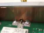
Yes, it is figured out. The problem is poor ground as you said. Cupper tape worked well, I could solder my board to the box thanks to cupper tape, it can be seen in attached figure.
improved_ground.jpg
What I understand from this problem is: The board should get its ground well, contact area between the board and the box should be maximized. It is extremely important that there should be direct connection from the board to the box around signal in/out regions on the board. Thank you very much for your suggestion and valuable contributions.
 

Status
Not open for further replies.

Part and Inventory Search

Welcome to EDABoard.com

Sponsor

Back
Top