Continue to Site

Welcome to EDAboard.com

Welcome to our site! EDAboard.com is an international Electronics Discussion Forum focused on EDA software, circuits, schematics, books, theory, papers, asic, pld, 8051, DSP, Network, RF, Analog Design, PCB, Service Manuals... and a whole lot more! To participate you need to register. Registration is free. Click here to register now.

RF Amp output distorted on load . Why?

Status
Not open for further replies.

Paul98

Member level 5
Joined
Sep 7, 2020
Messages
86
Helped
1
Reputation
2
Reaction score
0
Trophy points
6
Activity points
647
Hi!,

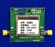
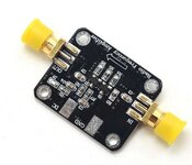
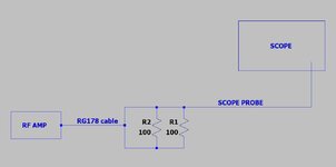
these days i am testing some RF amplifiers with a signal generator and one of these is the one in the picture but i have a problem. When I connect the output of this amp to the oscilloscope I see the sine wave correctly amplified and not distorted. Now this amplifier should have been made to work with 50Ohm loads. So I unplugged the oscilloscope from the amp output and connected a 50ohm dummy load. I did this to see how the amplifier behaved under load and the dummy load so I connected the oscilloscope probe and I saw something that has nothing to do with the output I had seen before on the oscilloscope. Completely distorted it is unusable . Same problem with a smaller black amplifier. If connected directly to the oscilloscope I see a perfect sine wave but if I connect the load it is a disaster. Where am I doing wrong?
 

Attachments

  • gatt.JPG
    gatt.JPG
    36.8 KB · Views: 126
  • gatt2.JPG
    gatt2.JPG
    26.7 KB · Views: 127

Solution
Any of the attenuators will work for you, don't expect the attenuation you set to be particularly accurate. They will do for altering the level, basically acting as a 'volume control' for a 50 ohm system.
The power meter is OK for low level signals, it is not going to be accurate either and will need an input attenuator to extend the maximum input making it more useful.
To make reliable RF measurements takes some care and good kit. What you have shown above will give you a rough idea of what is going on if you take care and understand the limitations of the devices.
A good set of attenuators will be useful asset. When I was at work I always had a set of at least the values recommended by FvM in my pocket, and used them almost daily.
Is your scope set for high impedance when you've got the load connected? If the scope is set for 50 ohms, then you've got a 25 ohm load on your amp.
 

The impedance on scope is not tunable andin this case is fixed to 1MΩ±2%, in parallel with 10pF±5pF . Here below the schematic used for measures. In simple i've made a dummy load as drawed and connected the probe on dummy load in that way.
 

Attachments

  • Gatt3.JPG
    Gatt3.JPG
    40 KB · Views: 129

Besides claiming correct load impedance you didn't give any useful information like frequency or power level used in your test. Measured waveform?
 

Signal input to amp is sine 10mv and frequencies form 1 to 50Mhz . No problem of wave distortion with the scope directly connected on the outoput. The problem comes when i use a 50ohm dummy load but why?
 

Assumption: 10mV is peak to peak
input = -5dBm approximately
amplifier gain 35dB
output should be +27dBm (0.5W)
Current into 50 Ohms for 0.5W O/P = 100mA rms
Current draw of amplifier 1, 35mA, need another 65mA.
The amplifier is being severely over driven, reduce the input level by about 20dB.
The open circuit output voltage at that input power is probably about the maximum it can deliver without significant distortion.
 
Depending on the design of your amplifier, it might
want a DC-block at input and/or output, to prevent
(say) source stage's output DC bias and destination
input stage from putting one or the other out of place.
Many RF amps do not want a direct ohmic 50 ohms
to ground plane at one end or the other.

I think that if those amps have SMAs then they are
meant for 50 ohms in and out (blocked if need be).
Z=1M at the far end could put the amp into clipping
if it was set up for full power into 50 ohms, and you
don't give it 50 ohms.

I expect if you gave us a 'scope shot of the munged
waveform, one of the "radio heads" might recognize
the symptoms. A shot of a good lineup wouldn't hurt
for context.
 

Yes he have sma connector and is declared to 50 Ohm, load.Unfortunately my Signal generator cannot produce voltage under 10mV but o can reduce this with a voltage divider right?. I will try some measure using voltage divider or other.
 

Usual LNA modules have input/output AC coupling, at least the black PCB has it.
According to my math 10 mV (rms p.d.) corresponds to -27 dBm, 10 mV e.m.f. to - 33 dBm. A good LNA should be able to process it without distortion, the low frequency gain can be however higher than specified 32 dB. In so far we would always check amplifier operation with lower input signal. You should have a set of SMA attenuators (e.g. 3, 6, 10, 20 dB) at hand.
Can i use a programmable attenuator instead fixed ones? If precise i can select the attenuation more precise. What do you think?


Any of the attenuators will work for you, don't expect the attenuation you set to be particularly accurate. They will do for altering the level, basically acting as a 'volume control' for a 50 ohm system.
The power meter is OK for low level signals, it is not going to be accurate either and will need an input attenuator to extend the maximum input making it more useful.
To make reliable RF measurements takes some care and good kit. What you have shown above will give you a rough idea of what is going on if you take care and understand the limitations of the devices.
A good set of attenuators will be useful asset. When I was at work I always had a set of at least the values recommended by FvM in my pocket, and used them almost daily.
 
Solution
Hi, the suggestion from @G4BCH and @FvM was right to return distortion-free output. Attenuator will solve the overdriving problem. Thank you.
 

Status
Not open for further replies.

Part and Inventory Search

Welcome to EDABoard.com

Sponsor

Back
Top