spiba
Junior Member level 2
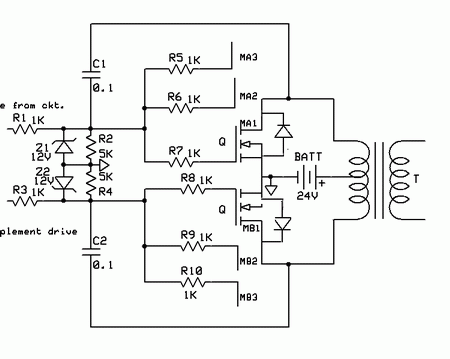
Normally in inverter circuits mosfets fail when another phase is connected accidently by electricians
to the output of an inverter .This leads to all mosfets connected in parrelal in both half bridge to Blow. Normal overload protection circuit of the inverter don't work under these conditions. Some manufacturers claim as their inverters design being Reverse phase protected .How to sense the different phase at the transformer output ( 230 Volts tap at output going to lighting load) and protect the mosfets ?
to the output of an inverter .This leads to all mosfets connected in parrelal in both half bridge to Blow. Normal overload protection circuit of the inverter don't work under these conditions. Some manufacturers claim as their inverters design being Reverse phase protected .How to sense the different phase at the transformer output ( 230 Volts tap at output going to lighting load) and protect the mosfets ?