Continue to Site

Welcome to EDAboard.com

Welcome to our site! EDAboard.com is an international Electronics Discussion Forum focused on EDA software, circuits, schematics, books, theory, papers, asic, pld, 8051, DSP, Network, RF, Analog Design, PCB, Service Manuals... and a whole lot more! To participate you need to register. Registration is free. Click here to register now.

[SOLVED] Response of a parallel RLC circuit to an AC current?

Status
Not open for further replies.

koushikr_in

Member level 2
Joined
Aug 18, 2004
Messages
42
Helped
1
Reputation
2
Reaction score
1
Trophy points
1,288
Activity points
356
Hi,

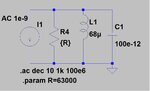
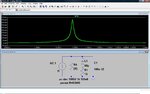
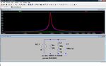
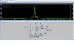
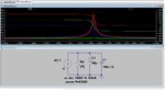
I simulated a simple RLC parallel circuit using LTspice. The circuit diagram and results are attached. A current source (1 nA) connected across parallel RLC. In the AC response, I expect all the current (1nA) to flow through resistor (63 kohms). But I find only 180 pA flowing through the resistor at resonance. Why is this so?


Thanks
Koushik
 

Attachments

  • Par RLC.jpg
    Par RLC.jpg
    38 KB · Views: 165
  • Par RLC Result.jpg
    Par RLC Result.jpg
    33.9 KB · Views: 167

Probably because your frequency step is too large.

A couple of other points - the current you are using is very small and the default absolute voltage & current tolerances of Spice could cause problems. Simply use 1A for the current source.

Also, if you are trying to simulate reality you should put the resistor in series with the inductor.

Keith
 
  • Like
Reactions: arthur0

    arthur0

    Points: 2
    Helpful Answer Positive Rating
Check the inductor model: Is it free of losses?
 

Yes Keith, you also have picked up a good point. Therefore, I always recommend to highlight the calculated points in the display in order to see if the resolution is good enough. On the other hand - everybody should see that something is wrong when he obeserves "edges" and other sharp transitions in the display. Something like that will never happen in reality (exceptions?).
LvW
 

Hi everyone,

Thanks for your reply. I increased the resolution of my spice (10000 points per decade) and current source changed to 1A. I still find the current through the 68 k resistor less than 500 mA. This is independent of whether I add a resistor in series with the inductor or not. Why is it so? The inductor and the capacitor are ideal elements.
 

Attachments

  • Par RLC.jpg
    Par RLC.jpg
    106.4 KB · Views: 140
  • Par RLC All Curr.jpg
    Par RLC All Curr.jpg
    103.4 KB · Views: 164

Atthough the inductor "loss" resistance has been suggested in the discussion by contributors, you should be clear about it's effect to drain part of the source current from the parallel resistor in resonance to feed the losses. Both of your plots have the 13 ohm series resistor. But with ideal L and C, this effect can't be seen. Thus I didn't understand which case you are describing. At least, you don't show a plot where it can be seen. My simple guess is, that you confused the simulation cases. Otherwise show the case, where the resistor current is considerably smaller in resonance, with ideal L and C elements.
 
  • Like
Reactions: arthur0

    arthur0

    Points: 2
    Helpful Answer Positive Rating
... current source changed to 1A. I still find the current through the 68 k resistor less than 500 mA.

One of (possibly) several reasons for this "funny" behaviour may be the following:
For AC analyses, in LTSPICE the AC value is specified with it´s amplitude - in contrast to all other simulation programs.
You should check what parameter is displayed on the screen (rms or something else?).
Another hint: display the current through L||C together with the current through R.
 

You should check what parameter is displayed on the screen (rms or something else?).
LTspice displays magnitude rather than rms values. Because the shown plot has an axis extend to negative values, it's implicitely clear, that the plot style is "cartesian" (real/imaginary amplitude) with imaginary part deselected. So in the "ideal" resonance case, the current is equal to source magnitude. And that's what I see, using the originally posted circuit, with an appropriate frequency step.
 

Hi all,

As suggested, I tried removing the resistor in series with the inductor. Now the simulation shows the entire current (1 A) flowing through 63 k at resonance. I guess the resistor in series to the inductor contributes to the loss by decreasing the effective Q.
 

Attachments

  • Par RLC_ideal.jpg
    Par RLC_ideal.jpg
    86.5 KB · Views: 123
  • Par RLC All Curr_ideal.jpg
    Par RLC All Curr_ideal.jpg
    96.9 KB · Views: 174

Status
Not open for further replies.

Part and Inventory Search

Welcome to EDABoard.com

Sponsor

Back
Top