Continue to Site

Welcome to EDAboard.com

Welcome to our site! EDAboard.com is an international Electronics Discussion Forum focused on EDA software, circuits, schematics, books, theory, papers, asic, pld, 8051, DSP, Network, RF, Analog Design, PCB, Service Manuals... and a whole lot more! To participate you need to register. Registration is free. Click here to register now.

Resistor saturation by DC???

Status
Not open for further replies.

neazoi

Advanced Member level 6
Joined
Jan 5, 2008
Messages
4,119
Helped
13
Reputation
26
Reaction score
15
Trophy points
1,318
Location
Greece
Activity points
36,918
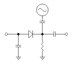
Hi I have built this little circuit and I notice a weird behaviour which I would like to discuss.

The rf generator works on HF. The resistor is 1k and the capacitors 100nf.

When the left port is left unconnected I measure about -1v DC at the left port and about 2vpp at the right port.
When a DC is applied to the left port, I measure a lower voltage (~1vpp) on the right port.

What is going on?

Is there any way that the DC that passes through the resistor somehow saturates it and causes more RF to flow through it to the ground instead of the right port?
 

Attachments

  • Capture.PNG
    Capture.PNG
    1.7 KB · Views: 66

When the left port is left unconnected I measure about -1v DC at the left port and about 2vpp at the right port.
When a DC is applied to the left port, I measure a lower voltage (~1vpp) on the right port.

What is going on?
Have no idea from your limited information
What are the two input voltages and frequencies to the top and left ports?
 

Hi,

This is quite expectable.
What worries you? What did you expect?

For DC you may omit the capacitors...

And unconnected nodes may float, means the voltage is not defined.

Klaus
 

    neazoi

    Points: 2
    Helpful Answer Positive Rating
This is quite expectable.
What worries you? What did you expect?

So is this the explanation? That when DC flows through a resistor, it's AC "permeability" changes?
That's what you mean?
 

Hi,

It's a standard diode resistor situation.

Again: what did you expect?

Klaus
 

You've been really informative thank you...
 

When the left port is left unconnected I measure about -1v DC at the left port and about 2vpp at the right port.
That's just the diode working as a rectifier.
When a DC is applied to the left port, I measure a lower voltage (~1vpp) on the right port.
If you apply a negative voltage, the diode junction capacitance will drop and you might get marginally more RF at the right.
If you apply a positive voltage, the diode will conduct and start to look more like a resistor so the input capacitor will start to shunt the signal.

All this depends on how much RF (we can guess to some extent by the -1V you see) and the polarity and amount of DC you apply. It isn't the resistor saturating that causes the effect you observe though.

Brian.
 

    neazoi

    Points: 2
    Helpful Answer Positive Rating
If you apply a positive voltage, the diode will conduct and start to look more like a resistor so the input capacitor will start to shunt the signal.

Thanks so much, this was puzzling me! Ok so it is RF leakage (both parts of the cycle, not just negative) to the left side of the circuit, when the diode conducts.

Is there any way I can apply a pure DC to the center point of the circuit and block RF from passing to the left?
See for example the middle bottom image in this picture (different experiments of mine) where I am trying to make an inverter gate.
The way I have figured out up to now, is to put a reverse shunt diode at the input and guide negative RF to the ground. I do not block it but I minimize it to reach the left port.

In this center bottom schematic, I have thought this as RF shunted to the ground when DC opens the diode that has it's cathode faced on the ground. But I can still sense some RF leaking to the left port and I do not why is that. You r explanation makes sense, although I still do not understand why RF is leaked to the left whereas there is a diode short to the ground?
 

Attachments

  • RFgate.PNG
    RFgate.PNG
    8.4 KB · Views: 59
Last edited:

How much the diode conducts depends on how much DC you apply. If the DC is below Vf, the diode will conduct on the input cycles taking it above Vf but if you 'saturate' the diode with DC current, it will behave more like a resistor. If you look back to your original post and think of the diode as a resistor you can see how it shunts the signal to ground through the input capacitor on the left.

I think what you are trying to do is make a simple diode RF switch rather than in inverter gate. The trick is to pass the signal through two back to back diodes in series. At the input and output use resistors or ideally chokes to ground to provide a DC path. At the junction of the two diodes feed the switching DC voltage, again through a resistor or chokes. The idea is that if you apply a voltage to make the diodes conduct, they become like low value resistors and the signal passes through. If you reverse the voltage the diodes look like low value capacitors and the signal is blocked.

Brian.
 

I think what you are trying to do is make a simple diode RF switch rather than in inverter gate. The trick is to pass the signal through two back to back diodes in series. At the input and output use resistors or ideally chokes to ground to provide a DC path. At the junction of the two diodes feed the switching DC voltage, again through a resistor or chokes. The idea is that if you apply a voltage to make the diodes conduct, they become like low value resistors and the signal passes through. If you reverse the voltage the diodes look like low value capacitors and the signal is blocked.

Yes I fully understand what you are saying. This won't produce the inverter function though, which is what needed.
My idea for this weird inverter is to switch the RF to different parts of the circuit. Upon no diode saturation (logic 0 input) RF flows to the right side and this causes a logic 1 at the output. Upon diode saturation (logic 1 at the input) RF finds a better path to the ground through the saturated diode instead of the right part of the circuit. This causes a logic 0 at the output. This is how this weird circuit of mine works.

I have done tests in the scope and it does work, but I was hoping to isolate the input of the circuit from leaked RF.
An idea was to use a reverse shunt diode at the input to limit the negative pard of the RF that leaks to the input. This worked somehow but it kind of reduced a bit the logic 1 output level, still ok though.
Another idea would be to add a high value choke in series with the resistor, which should filter out RF.

If you have any ideas let me know this is a very interesting experiment.
 

I'm confused when you say logic '0' or logic '1' at the output. By logic state are you referring to the presence or absence of signal?
If so, be careful with 'shunt switches' using diodes to steer signals into ground because they have no isolation, they literally short the signal out. You will also get clipping of the signal unless you provide a reverse bias voltage to keep the switch 'on', just removing the DC turns the circuit into a rectifier.
My idea for this weird inverter is to switch the RF to different parts of the circuit
Diodes are quite commonly used for signal steering, many receivers use them to direct signal paths through different filter circuits for example. They use the two diode approach I described earlier though but add the filter between the diodes.

Brian.
 

    neazoi

    Points: 2
    Helpful Answer Positive Rating
I'm confused when you say logic '0' or logic '1' at the output. By logic state are you referring to the presence or absence of signal?
If so, be careful with 'shunt switches' using diodes to steer signals into ground because they have no isolation, they literally short the signal out. You will also get clipping of the signal unless you provide a reverse bias voltage to keep the switch 'on', just removing the DC turns the circuit into a rectifier.

By logic 1 I mean high voltage. By logic 0 I mean a signal close to 0v.
The center diode indeed shorts the RF signal to the ground. When it is not forward biased, it clips the RF signal on the positive cycle, if this can overcome the diode forward voltage and set it to conduction. A solution is to use more series diodes dependent on the level of RF signal applied.

I think that my problems with this schematic are related to the RF leaking through the input diode (negative cycle) ans back to the input (left port). This negative rectified voltage is combined to the preceding stages positive DC and pulls this down. Here is for example two such gates connected in series, so as to see what I mean.

I think I have to figure out how to solve this issue, any ideas?
 

Attachments

  • Capture.PNG
    Capture.PNG
    3.8 KB · Views: 52
Last edited:

Hi,
I think that my problems with this schematic are related to the RF leaking through the input diode (negative cycle) ans back to the input (left port). This negative rectified voltage is combined to the preceding stages positive DC and pulls this down.
I don't call this "leaking". It' the normal forward biased diode operation, where the anode is more positive than the cathode.
The diode simply is conductive.

Klaus
 

Hi,

I don't call this "leaking". It' the normal forward biased diode operation, where the anode is more positive than the cathode.
The diode simply is conductive.

Klaus

You are absolutely right.
I think I have made some progress on it. In this new schematic I clip the oscillator signal, but only the negative portion of it. See the left clipping diode right below the oscillator. However, I put more series diodes to the ground, so as not to clip the positive portion of the oscillator signal, which is needed. Now the positive portion does it's job on the right voltage doubler part, whereas the clipped negative portion is much smaller when it passes the left diode. The small amount that passes to the input through the left diode is further filtered and brought closer to zero volts (I use low dropout diodes). The 4 series diodes can still shunt RF to the ground effectively, but a bit more current is needed of course. The good thing about embedding such a clipper to the gate, is that you can automatically compensate for different oscillator levels (above the positive clipping point).

How do you find this idea?
 

Attachments

  • RFgate.PNG
    RFgate.PNG
    3.6 KB · Views: 53

Hi I want to ask something. Connecting two such gates in series did not succeed. I believe that there is not enough current out of the small can oscillators that I have used, so there is a big voltage drop at the output voltage coubler.

How can I measure the RF output current of these oscillators, just load them with a resistor and measure... what?

How efficient is this peak detector in converting RF power into voltage/current?
 

Status
Not open for further replies.

Similar threads

Part and Inventory Search

Welcome to EDABoard.com

Sponsor

Back
Top