Continue to Site

Welcome to EDAboard.com

Welcome to our site! EDAboard.com is an international Electronics Discussion Forum focused on EDA software, circuits, schematics, books, theory, papers, asic, pld, 8051, DSP, Network, RF, Analog Design, PCB, Service Manuals... and a whole lot more! To participate you need to register. Registration is free. Click here to register now.

Resistor material identification

Status
Not open for further replies.

Cap_J

Newbie
Joined
Jun 8, 2019
Messages
5
Helped
0
Reputation
0
Reaction score
0
Trophy points
1
Activity points
48
Hello,
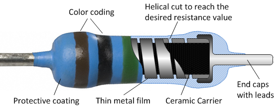
I would like to identify the type of resistor in the photo on the left.

20211006_163135.jpg


After removing the paint, I can see a dark/graphite cylinder with a short "bar" (gouge/cut). Would this be a carbon resistor? Unfortunately I wasn't able to cut/split it with pliers to check the inside.

Thank you in advance for your answers.

Regards.
 

Hello Cap_J,
I'm unsure of the material the resistor on the left is made of, but those
types are commonly the fusible ones. Designed not to flame up. Just go
open circuit instead.
Regards,
Relayer
 

Sir Cap_ j . . . . .
Unfortunately I wasn't able to cut/split it with pliers to check the inside.
And you WON'T be able to check inside . . . .because . . .
The insides of that cylinder is being bisque ceramic and having metal deposition around the whole cylinder.
The resistance is that whole external coating.
Then on that particular unit if you were to install /crimp on metal end caps with their attached leads you would then read the linear cylindrical widths resistance from end to end.
BUT note, that they have used a laser to cut a slanting spiral path starting at the left end, with the resistance "vaporization " groove stopping at the 2.2 ohm spot.
(This is much easier to visualize, if that spiral had made a couple of bands to be seen.)
To wit . . . . .
metal_film_resistor_schematic.png

On your unit they just hardly got started on a spiral and they had already met resistance specs.

73's de Edd


.
 

The spiral lines molded in the thermal conductive substrate is masked as the insulator path. Vacuum vapor metal deposition then coats the rest of the path that leaves a low resistance path for power to be evenly distributed. The metal film (possibly sputtered NiCr) or foil thickness and the path length of the spiral insulator determine the increased resistance from the increased path length. This also raises the parasitic inductance about 0.5nH/mm.

After the mask is removed leaving the insulated spiral , laser trimming can improve the accuracy from 10% down to 0.1%

These are the attributes which increase cost in a 2W TH resistor with plating thickness, laser cut width and chemical coatings.
Flame Retardant, Flame Proof, Fusible, Pulse Withstanding, increased Safety, fusing breakdown voltage


The fuse time depend on the design and ratio of excess/rated power. 50:1 might be 10 seconds.
MF power resistors are cheaper than WW and lower noise than Carbon and CF.
 
Last edited:

Status
Not open for further replies.

Part and Inventory Search

Welcome to EDABoard.com

Sponsor

Back
Top