Welcome to our site! EDAboard.com is an international Electronics Discussion Forum focused on EDA software, circuits, schematics, books, theory, papers, asic, pld, 8051, DSP, Network, RF, Analog Design, PCB, Service Manuals... and a whole lot more! To participate you need to register. Registration is free. Click here to register now.
I found just simple circuit with resistor 470 - LED - about 2,0V - resistor 470. The voltage is probably 9V. I understand why there is the first resistor before LED, but I do not know there's why another one?
I found just simple circuit with resistor 470 - LED - about 2,0V - resistor 470. The voltage is probably 9V. I understand why there is the first resistor before LED, but I do not know there's why another one?
The second resistor has the same function as the first one...the current limiting.
No matter how much resistor you put in series, the effect will be current limiting, however their power rating will increase then.
Thanks, for replies. But I understand how resistor works. The problem I do not understand is on page 92 in Myke Predko's books - Digital Electronics Demystified. If anybody has that book, try to explain the scheme to me please.
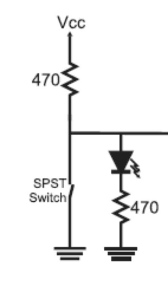
This circuit has two functions:
1- To generate an acceptable logical level according to the switch position and
2- Turn the led on or off according to the logical level.
Please remember that the voltage across the led is only about 2V and this is not an acceptable logical level. So, when it is turned ON (switch open) the lower resistor adds some voltage to the output which reaches about 3,6V (acceptable). When the switch is closed the upper resistor protects it by limitting the total current flowing through it.
Added after 1 minutes:
No one could ever mind what your circuit was so, please, try to upload your circuit when asking a question.
Resitor has IR drop. For the circuit given, voltage across each resitor is =(9-2)/2=3.5 where 2V is the LED voltage. Thus output voltage=diode voltage+resitor drop=2+3.5=5.5V (when switch is open). Hence it is the resistor which is adding to the voltage at the output.
This site uses cookies to help personalise content, tailor your experience and to keep you logged in if you register.
By continuing to use this site, you are consenting to our use of cookies.