Welcome to our site! EDAboard.com is an international Electronics Discussion Forum focused on EDA software, circuits, schematics, books, theory, papers, asic, pld, 8051, DSP, Network, RF, Analog Design, PCB, Service Manuals... and a whole lot more! To participate you need to register. Registration is free. Click here to register now.
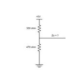
When there is a voltage source as here (0 and 5 V), then for analysis purposes you connect them together, as a perfect voltage source has a 0 Ohm impedance. So once you do that, it becomes a simple combination of two parallel resistors. For two resitors, R1 and R2, the combination is R1*R2/(R1+R2). For n resistors in parallel, one uses the formula 1/R=1/R1 + 1/R2 + 1/R3 .... 1/Rn.
Someone else has already worked it out for you, but I thought I'd explain why his/her method is correct.
cks is right. And remember to include a good blocking capacitor from the top point to ground. At RF, many people forget to use several parallel capacitors to cover from DC to a maximum frequency. A good idea is to connect 10 uF, 0.1 uF and 10 nF in parallel- this makes a good RF short.
This site uses cookies to help personalise content, tailor your experience and to keep you logged in if you register.
By continuing to use this site, you are consenting to our use of cookies.