Continue to Site

Welcome to EDAboard.com

Welcome to our site! EDAboard.com is an international Electronics Discussion Forum focused on EDA software, circuits, schematics, books, theory, papers, asic, pld, 8051, DSP, Network, RF, Analog Design, PCB, Service Manuals... and a whole lot more! To participate you need to register. Registration is free. Click here to register now.

[SOLVED] Resistor Calculation in LED Array

Status
Not open for further replies.

tjpc

Newbie level 4
Joined
Apr 20, 2015
Messages
5
Helped
0
Reputation
0
Reaction score
0
Trophy points
1
Activity points
57
Hello to all from a noob!

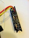
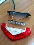
I'm trying to fix a broken moped tail light (led based). A power spike burned a resistor so bad, it's impossible to read the colour codes on it.

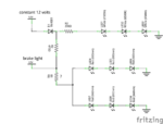
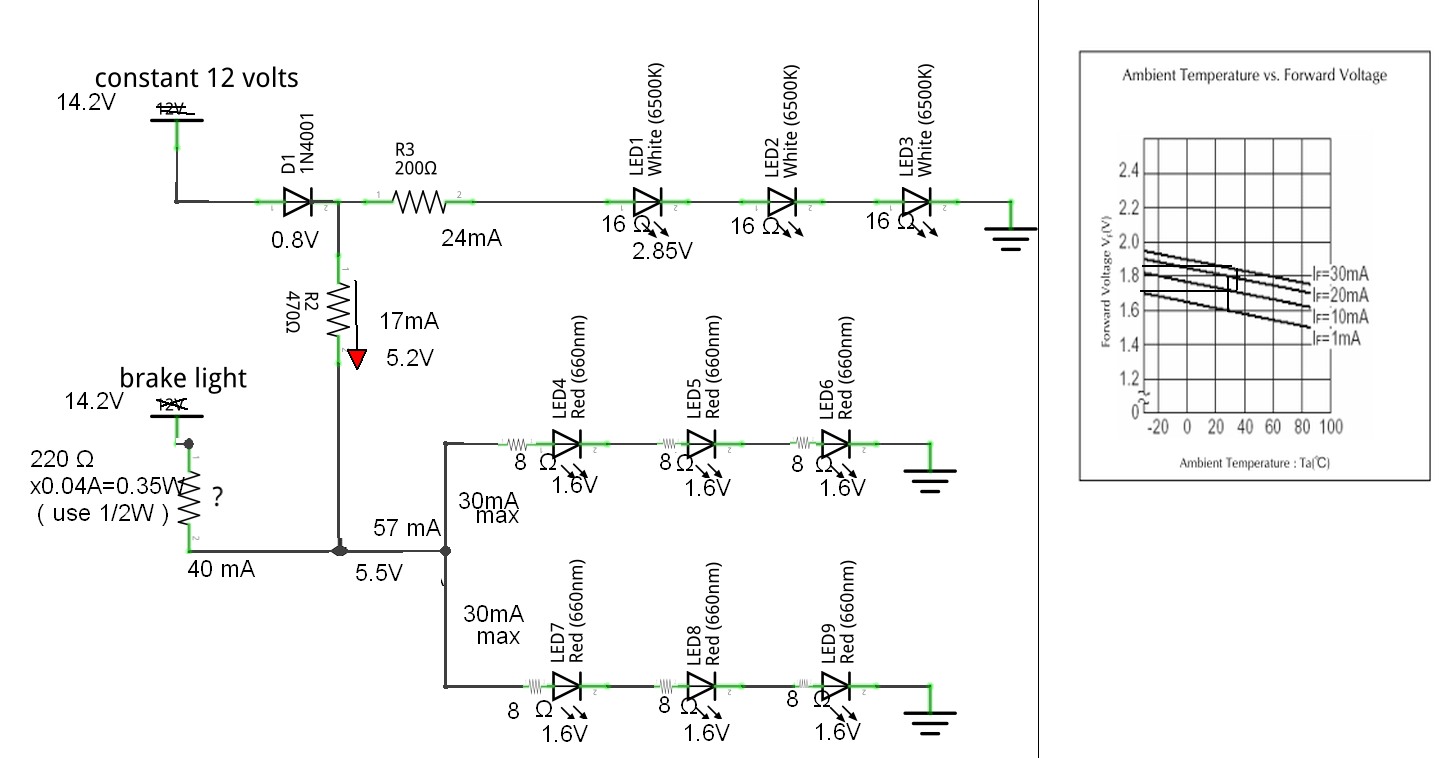
Now I would really appreciate some help in calculating the needed resistance value so I can replace the resistor. I've drawn a schematic of the circuit based on my poking-around-with-a-multimeter skills :grin: I'll attach the drawing to clarify the circuit.

The light works with two 12 volt power wires: a constant, always-on 12 volt wire that supplies power for the license plate light (3 white leds, LED1 to LED3) and also power for the six red tail light leds. The brake light wire provides 12 volts when braking, and from what I understand it makes the red leds (LED4 to LED9) shine brighter than normal by bypassing the R2 resistor.

The blown resistor is R1 (marked with a ?) in the schematic. What resistance value should it have? I've tried to read up about resistors in series and parallel, but this gets too complicated..

TL;DR: What should the value of R1 be?

Any help would be appreciated!
-Tommy
 

Attachments

  • breaklight_schem.png
    breaklight_schem.png
    84.4 KB · Views: 112

Big LEDs can be very bright with lots of current. Ordinary LEDs are 5mm in diameter and are rated with a current of only 20mA but 30mA is their maximum allowed current for them to be fairly bright.
Assuming that the "12V" is a 13.8V fully charged battery then the diode reduces the available voltage to 13.0V. Red LEDs use about 2.0V each so the three in series use 6V. Then the brake resistor has 13V - 6V= 7V across it and has two 30mA LED strings totalling 60mA. The resistor value is calculated to be 7V/60mA= 117 ohms which is not a standard resistor value, use 120 ohms. The power heating the resistor will be 7V squared/120 ohms = 0.4W. A half Watt resistor will be very hot so use a 1W resistor.

EDIT: I forgot. Modifying lighting on a vehicle is illegal. You must use what the manufacturer used so that the brake light is the same brightness as the Moped was tested with. Don't tell a policeman you worked on the lights.
 
  • Like
Reactions: tjpc

    tjpc

    Points: 2
    Helpful Answer Positive Rating
Usually the Vf of bright red LEDS is 1.9 to 2V but can be as high as 2.4V
The max [continuous] current is usually 20mA but can be higher [25mA to 30mA].
So there are 2 unknowns - we are guessing.
You imply the voltage is 12V but usually this is the nominal voltage. It can be higher when the conventional battery is fully charged, and even higher when being re-charged. It would be safer to assume 14V.

You can measure the Vf and that would help.

The formula for the resistor is {Vs - total Vf} / I where Vs is the voltage, total Vf is sum of the Vf's of the LEDs, and I is the current You should double the current as there are two 'strings' in parallel

The power rating [W] is at least 2 * {Vs - total Vf} * I

You can use http://ledcalc.com/

BTW
It is considered BAD practice to not to have a resistor for each 'string' - LED4 to LED6 should have it's own resistor and LED7 to LED9 should have it's own resistor. I would replace R1 with 2 resistors; one for the first string[LED4 to LED6] and a second for the other string [ LED7 to LED9].
 
Last edited:
  • Like
Reactions: tjpc

    tjpc

    Points: 2
    Helpful Answer Positive Rating
Choice of LEDs affects choice of R. and if Moped has a generator at 14.2V, RED LEDs need 2 current limiting Rs 10mA for dim on 3S2P array and 60mA Max on bright.

I chose R to be 220 Ω 1/2W for BRAKE LED R

This is a rather poor design because;
a) the LED R burnt out
b) the RED LEDs are probably dimmer now from thermal damage.
3) no precise current regulation
4) inefficient
5) too cheap to use 5 Red per string & a 2 step current limiter

Assuming 30mA max LEDs with 647 to 660 nmD HB RED

The WHite take 17mA typ. and the RED will take 30mA on Brake and 5mA per string on dim.

8290071400_1429600169.jpg


Also the WEB LED R calculators ignore ESR of LEDs and are very conservative.

Assumptions for Red and White LEDs are given for good quality LEDS ( not worst case junk)
- the low current Vth voltage is given ( null current asymptote)
- with the ESR was used to calculate Voltage and currents.

Note ESR drops with substrate wavelength for same size 30mA max chip.

Test verification will tune final results.
 
  • Like
Reactions: tjpc

    tjpc

    Points: 2
    Helpful Answer Positive Rating
Thanks for all quick responses and useful remarks on the subject!

The white leds are quite small, 3 mm I think. The red ones are larger square shape leds with four legs. I'll attach a couple of photos of the whole assembly to clarify further.

I agree with you that the design may be poor using just one resistor for the red led strings, but this is what I found when popping open the light. Most examples I found on the web used separate resistors for each led string.

I also think think the resistors look quite small, are they 1/4 watts?

Based on your answers the choices seem to be either 120 ohm 1 watt resistor or a 220 ohm 1/2 watt...

Thanks,
Tommy
 

Attachments

  • mopedlight1.jpg
    mopedlight1.jpg
    71 KB · Views: 94
  • mopedlight2.jpg
    mopedlight2.jpg
    102 KB · Views: 102

Based on your answers the choices seem to be either 120 ohm 1 watt resistor or a 220 ohm 1/2 watt...

It depends on the Vf of the LEDS, and this is critical as the sum of the Vf's is close to the supply voltage.

You have not provided the Vf.
 

The square LEDs are Philips Luxeon SuperFlux or a cheap Chinese copy. I was given some red Luxeon ones for helping a guy in a forum. Their maximum allowed current is 70mA if their pins are soldered to plenty of copper on a pcb for cooling and the air is not hotter than 25 degrees C.
I have 36 on them on Veroboard in the case for a compact cassette tape with lots of cooling holes and legs to allow cool air to come from beneath and boy-oh-boy do they ever get HOT at 53mA. The project was to be an indoor "night light" but it is so bright it lights the entire neighbourhood.
 

Attachments

  • Luxeon SuperFlux LED.jpg
    Luxeon SuperFlux LED.jpg
    4.8 KB · Views: 141
  • nightlight.JPG
    nightlight.JPG
    19 KB · Views: 91
  • Like
Reactions: tjpc

    tjpc

    Points: 2
    Helpful Answer Positive Rating
these 70mA TOPLEDs have better thermal conduction to leads than 5mm radial, but unless you use a large copper area heatsink, you can barely run 50 mA, thus out of favour now towards SMD. But Brake lights dont stay on long.

So I would revise my recommendation from 30mA to 60mA per LED max and reduce R from 220 to 60 Ohm at 1/2W dissipation. or two 120 Ω in // 1/4W

THey dont make 70mA TOPLEDs in 660 nmD so I am suspecting they use 624 nmD which is closer to 660 nmP which people often confuse.

This drop raises the ESR and Vth value assumptions. to 1.8 Vth & 10 Ω typ for Vf=2.5V
Thus with 100 mA over a 6V drop on R , I get 60 Ω & 600mW , so two 120 Ω in parallel 1/4W might get hot briefly but with copper heatsink, be ok.
 
  • Like
Reactions: tjpc

    tjpc

    Points: 2
    Helpful Answer Positive Rating
Thanks for the input again!

As can be seen in the photos I attached, there are no heatsinks or large copper cooling areas for the leds and the circuit board is packed inside a waterproof (not anymore :-D ) plastic housing, so there's not much cooling provided here.

I think I'll try that two 120 ohm resistors in parallel solution and see how it goes.

I'll report back when I've tested it.

-Tommy
 

Or even three 180R or four 240R to spread the heat when Brake light is on.

Or even better a TO-220 ADJ-LDO with a current limit R to regulate CC mode. to 100mA or so.
if 1.25V ref like LM317 then 12R using 1/4W
 
  • Like
Reactions: tjpc

    tjpc

    Points: 2
    Helpful Answer Positive Rating
But Brake lights dont stay on long.
Haven't you noticed that some people drive with their brakes on all the time! I betcha they need brake replacements often. Think about all the fuel they are wasting, like my neighbour who has the furnace and air conditioning on in her house at the same time.
 

I must drive an area of conscientious drivers, they just don't move when there is time to go. But then they wave by honking at me sometimes.

I think brake light brightness should be controlled by brake fluid pressure like CPU fan speed is controlled by temp. to discern a normal stop from a panic stop.

LEDs are way too bright in general at night too. They ought to regulate it with photo sensors to avoid the light pollution.
 

LEDs are way too bright in general at night too. They ought to regulate it with photo sensors to avoid the light pollution.
For years, Jeep and Chrysler cars use undimmed high beams for daytime running lights that blind oncoming drivers when there is cloudy weather. Kia and Volkswagen cars are copying them now.
Many people who drive cars without automatic lighting when it gets dark (my car and $1.00 solar garden lights are automatic) do not bother turning on the lights at night because they see the front beams shining and wrongly think the rear lights are also turned on.
 

Tommy,
The resistor didn't burn from "power spike", most likely you have a fault with the switch and the brake light is on all the time. You better check that too. When audioguru was driving behind you he saw your brake lights on all the time but he thought that you are 'one of those drivers'.
 

For years, Jeep and Chrysler cars use undimmed high beams for daytime running lights that blind oncoming drivers when there is cloudy weather. Kia and Volkswagen cars are copying them now.
Many people who drive cars without automatic lighting when it gets dark (my car and $1.00 solar garden lights are automatic) do not bother turning on the lights at night because they see the front beams shining and wrongly think the rear lights are also turned on.

As I recall all cars with DTL high beams put them in series or used a 50% chopped DC for 1/2 Voltage, which makes them last longer and reduces glare at twilight. I've never seen undimmed HB's for DTL, they were all half bright for single beam lamps.

I also recall when 1 headlight is out or dim, people are noticed more than with the required DTL headlights mandated in Canada. I even remember people flashing their headlights at me on the #1 Canada divided highway when I was cruising back home to WInnipeg with a dead MGB generator after 24hrs of non stop driving from Ottawa. ( Turning on the headlights caused the ignition to fail with the battery on its last legs. ) circa 1970
 

I've never seen undimmed HB's for DTL, they were all half bright for single beam lamps.
Then why are daytime running lights on Jeep and Chrysler cars so much brighter than most other cars? They even turn off the headlight that has the turn signal turned on so it can be seen.
 

Tommy,
The resistor didn't burn from "power spike", most likely you have a fault with the switch and the brake light is on all the time. You better check that too. When audioguru was driving behind you he saw your brake lights on all the time but he thought that you are 'one of those drivers'.

The moped in question is not my own, it belongs to my sister's son (I'm sure there's an english term for this kind of relative). I'm already a 'big boy' (a.k.a adult) :-D.

The owner told me the light broke when the voltage regulator broke down on the moped, causing overvoltage in the electronics system. Checking the switch and brake light operation is probably still a good idea, so I'll tell him to check that too, just in case.

Thanks for the tip!
 

Hi all,
As i have observed during the night time all the vehicles will be having the red led lights ON which are dim while they are travelling and as soon as the the brakes are applied the intensity of the light increases and you can come to know that there is a break applied by the driver.So when you are designing a brake circuit you need to change the intensity of LED as required.So try to push more current when brake is applied.So keep two resistors in series during a travelling mode and when the driver applies a brake the intensity should change so a parallel resistance to the once kept in series will increase the current and decrease the resistance proportionately.
 

Your sister's son is your nephew, your sister's daughter is your niece.

Brake lights work even in bright sunlight when the dimmed rear lights are not turned on.
 

I went for the 3x180 ohm resistors in parallel on this one, and initial tests on the moped showed that they worked perfectly!

Thanks to all for contributing with great help!

-Tommy
 

Status
Not open for further replies.

Similar threads

Part and Inventory Search

Welcome to EDABoard.com

Sponsor

Back
Top