Continue to Site

Welcome to EDAboard.com

Welcome to our site! EDAboard.com is an international Electronics Discussion Forum focused on EDA software, circuits, schematics, books, theory, papers, asic, pld, 8051, DSP, Network, RF, Analog Design, PCB, Service Manuals... and a whole lot more! To participate you need to register. Registration is free. Click here to register now.

Resistance measurement/display without LCD, needle meter or 7-segment led?

Status
Not open for further replies.

neazoi

Advanced Member level 6
Joined
Jan 5, 2008
Messages
4,122
Helped
13
Reputation
26
Reaction score
15
Trophy points
1,318
Location
Greece
Activity points
36,951
Hi I want to investigate if there is a simple way of measuring a resistance by having a very primitive display type that can be homemade.
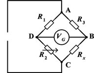
One way I am thinking is to have a decade resistance network and compare the unknown resistance to be measured with different decade resistance values. if the two resistances are equal then lit a led for example.
So is there any way I can do this comparison, compare 2 resistances that way?
 

Use a good current source an a ICL7107 voltmeter.

Klaus
 

    neazoi

    Points: 2
    Helpful Answer Positive Rating
Hm.. I think I found a way that matches the amount of simplicity I was looking without any decade resistors.
There must be a pre-calibrated voltage scale around the potentiometer. It is a voltmeter but I think it can easily be converted to resistance meter by replacing R1 with the unknown resistance to be measured. However, I would love to see how this D1 will behave (how accurate it can be) and if I can replace D1 with a discrete circuit.

Some kind of discrete Schmidt trigger comes into mind...
Perhaps this is all that is needed, when the input voltage passes the trigger point then fire the LED.
But I have not seen any of these that can fire in low voltages. Any ideas?
 

Attachments

  • simple voltmeter.png
    simple voltmeter.png
    24.6 KB · Views: 153

Wheatstone bridge?

Brian.
It requires a needle meter for zero adjustment. The whole point of going to that trouble is something simple, that lacks such a movement.
 

No it doesn't - use a simple audio oscillator as the source and earphone/loudspeaker across the arms. When the bridge is balanced the audio will be cancelled.

Brian.
 

    neazoi

    Points: 2
    Helpful Answer Positive Rating
No it doesn't - use a simple audio oscillator as the source and earphone/loudspeaker across the arms. When the bridge is balanced the audio will be cancelled.

Brian.
Can't I use DC as source (on A and C points) and a small incandescent bulb at Vg ? Won't it have the same result Brian?
Or even better, a set of anti-parallel LEDs to also indicate whether RX is smaller or larger than the R2 setting.

Is there any way I can use this (or another bridge type) to measure voltage?
 

Attachments

  • Wheatstonebridge.jpg
    Wheatstonebridge.jpg
    23.9 KB · Views: 113
Last edited:

What are your goals -

1) Accuracy ?
2) Range of resistance to be measured, compared ?
3) Compare accuracy ?
4) Rough cost for design ?

Regards, Dana.
 

you have the crux of the problem when you said
"But I have not seen any of these that can fire in low voltages." in post #3

whatever comparison you make, audio, LED, bulb, etc, will have some region
where there will be no signal
depending one the process, that region will be smaller or larger

listening to an audio signal, there will be some point where it simply will not be loud enough to hear
looking for a light, there will be some region where it simply isn't bright enough to see
LEDs need some voltage just to conduct - maybe you could use a few to compensate for that issue?
if these regions are within your accepted tolerance, then you're good

there is also the problem of small resistances where the resistance you want to measure is smaller than the tolerance of your circuit
likewise, the problem of large resistances, where the resistance reduces the current to essentially zero

i think you need to answer Dana's questions in post #8
 

Make a comparator from a logic gate. The output turns on one or the other led, depending on whether your unknown resistor (DUT) is greater or lower than your resistance decade box (potentiometer).
The change of state is automatically set where the input crosses 1/2 supply voltage. Therefore when the led's change, that is where the 2 resistances are equal.
Use caution if your unknown resistor is very low ohms. A 4069 IC (hex inverters) works with supply voltage down to 3V, which can reduce risks.

invert-gate acts as comparator of 2 resis (output is 2 led's).png
 
Last edited:

Can't I use DC as source (on A and C points) and a small incandescent bulb at Vg ? Won't it have the same result Brian?
Or even better, a set of anti-parallel LEDs to also indicate whether RX is smaller or larger than the R2 setting.
As has been explained, yes these alternatives will work provided you can give them enough current to visibly and reliably be seen. The bridge is a nulling circuit, it give no output when the resistances are equal but it the lamp/LED has a minimum operating voltage or current and the values in the bridge can't provide it, they simply won't operate. An incandescent lamp probably needs 10s of mA to light up, an LED at least 1mA and 1.6V so both will fail to show any result unless the resistor values are low enough and the LED in particular will have a wide 'dead band' where insufficient voltage is available to start it conducting.

The audio idea isn't as daft as first seems because our ears are quite sensitive to low audio levels so high impedance headphones or an amplifier and loudspeaker will be quite accurate. We can also easily find the center spot between settings where it starts to become audible if necessary. It worth noting that the bridge method will also work with capacitors and inductors, the other methods won't.

Brad's idea is good but not necessarily accurate. Obviously a Schmitt input gate wouldn't work and standard logic gates have a zone around their logic threshold which is poorly defined. The difference between low Vin and High Vin would create an area of uncertainty which is unpredictable and probably sensitive to supply and temperature changes. You could however use a comparator but it may need positive and negative supply rails for best performance.

Brian.
 
Last edited:

Status
Not open for further replies.

Similar threads

Part and Inventory Search

Welcome to EDABoard.com

Sponsor

Back
Top