Continue to Site
Follow along with the video below to see how to install our site as a web app on your home screen.
Note: This feature may not be available in some browsers.
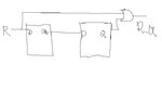
Hi the attached picture shows a reset where the reset is removed syncronously. What about the rest of this two flip fllops that works as a synchronizer.
You either didn't read or not understand it.That paper and these are known to me. You are not answering the question.
You either didn't read or not understand it.
The usual reset synchronizer known from literature, which is also shown in the sunburst paper is different from your scheme. It connects the asynchronous reset (or preset, depending on the reset polarity) of the synchronizer FFs to the reset input.
In your scheme, if you prefer it for some reason, you can simply leave the reset unconnected. But you should connect the clock, by the way.
In your scheme, if you prefer it for some reason, you can simply leave the reset unconnected. But you should connect the clock, by the way.
In the Figure both FF's are FF with synchronous resets.
Data will be driven with mux with reset as select line or with NAND or AND gates
Check below links to know how data are driven in FF with sync.resets
All About Reset
Verilog Coding Styles for Synthesis
Viewing the thread with one year distance, I think the main problem is that besides an incomplete schematic, no specific purpose of the circuit (e.g. related to standard reset synchronizers from literature) has been mentioned. Thus we can only guess about expectable clock and reset input waveforms. The question "should the FF resets be connected" (to the same reset driving the D input?) brings up the counter question: What's the reason not to use a standard reset synchronizer?