Continue to Site

Welcome to EDAboard.com

Welcome to our site! EDAboard.com is an international Electronics Discussion Forum focused on EDA software, circuits, schematics, books, theory, papers, asic, pld, 8051, DSP, Network, RF, Analog Design, PCB, Service Manuals... and a whole lot more! To participate you need to register. Registration is free. Click here to register now.

[PIC] Request For CAN information.

Status
Not open for further replies.

Zong Zai

Newbie level 3
Newbie level 3
Joined
Sep 5, 2014
Messages
3
Helped
0
Reputation
0
Reaction score
0
Trophy points
1
Visit site
Activity points
25
Hi,

Good morning every buddy.

I had try to touch about CAN communication for PIC32. I'm unfamiliar to CAN. Before this i had using rs232 , i2c and rs485 for communication, but now wan to use CAN. It is difference with i2c, for example i2c transmit data bu using the word Masterputs , masterwrite , slaveput , slaveget and receive, but for CAN case i didn't get the certain word to transmit or receive. So any buddy can help to explain for me??
Thank you!
 

Hi horace,

Thanks for your response, as you mean that if i set my microcontroller will be take action when receive the certain command, right?
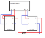
I wan to use CAN to communicate from a PIC32 to another PIC32.
I show you my wiring. Untitled.png
I wan to use CAN1 transmit command to CAN2 and CAN2 transmit to CAN1.
Any idea?

Code:
void CAN1Init(void)
{

	CAN_BIT_CONFIG canBitConfig;
	CANEnableModule(CAN1,TRUE);

	CANSetOperatingMode(CAN1, CAN_CONFIGURATION);
	while(CANGetOperatingMode(CAN1) != CAN_CONFIGURATION);

	canBitConfig.phaseSeg2Tq            = CAN_BIT_3TQ;
	canBitConfig.phaseSeg1Tq            = CAN_BIT_3TQ;
	canBitConfig.propagationSegTq       = CAN_BIT_3TQ;
	canBitConfig.phaseSeg2TimeSelect    = TRUE;
	canBitConfig.sample3Time            = TRUE;
        canBitConfig.syncJumpWidth          = CAN_BIT_2TQ;

    CANSetSpeed(CAN1,&canBitConfig,SYS_FREQ,500000);
    CANAssignMemoryBuffer(CAN1,CAN1MessageFifoArea,(2 * 8 * 16));
    CANConfigureChannelForTx(CAN1, CAN_CHANNEL0, 8, CAN_TX_RTR_DISABLED, CAN_LOW_MEDIUM_PRIORITY);
    CANConfigureChannelForRx(CAN1, CAN_CHANNEL1, 8, CAN_RX_FULL_RECEIVE);

    CANConfigureFilter      (CAN1, CAN_FILTER0, 0x201, CAN_SID);
    CANConfigureFilterMask  (CAN1, CAN_FILTER_MASK0, 0xFFF, CAN_SID, CAN_FILTER_MASK_IDE_TYPE);
    CANLinkFilterToChannel  (CAN1, CAN_FILTER0, CAN_FILTER_MASK0, CAN_CHANNEL1);
    CANEnableFilter         (CAN1, CAN_FILTER0, TRUE);

    CANEnableChannelEvent(CAN1, CAN_CHANNEL1, CAN_RX_CHANNEL_NOT_EMPTY, TRUE);
    CANEnableModuleEvent (CAN1, CAN_RX_EVENT, TRUE);
    INTSetVectorPriority(INT_CAN_1_VECTOR, INT_PRIORITY_LEVEL_4);
    INTSetVectorSubPriority(INT_CAN_1_VECTOR,  INT_SUB_PRIORITY_LEVEL_0);
    INTEnable(INT_CAN1, INT_ENABLED);
    CANSetOperatingMode(CAN1, CAN_NORMAL_OPERATION);
    while(CANGetOperatingMode(CAN1) != CAN_NORMAL_OPERATION);

}
void CAN2Init(void)
{
    CAN_BIT_CONFIG canBitConfig;
	CANEnableModule(CAN2,TRUE);

	CANSetOperatingMode(CAN2, CAN_CONFIGURATION);
	while(CANGetOperatingMode(CAN2) != CAN_CONFIGURATION);
	canBitConfig.phaseSeg2Tq            = CAN_BIT_4TQ;
	canBitConfig.phaseSeg1Tq            = CAN_BIT_4TQ;
	canBitConfig.propagationSegTq       = CAN_BIT_4TQ;
	canBitConfig.phaseSeg2TimeSelect    = TRUE;
	canBitConfig.sample3Time            = TRUE;
    canBitConfig.syncJumpWidth          = CAN_BIT_3TQ;

    CANSetSpeed(CAN2, &canBitConfig, SYS_FREQ, 500000);
    CANAssignMemoryBuffer(CAN2,CAN2MessageFifoArea,2 * 8 * 16);
    CANConfigureChannelForTx(CAN2,CAN_CHANNEL2,8,CAN_TX_RTR_ENABLED,CAN_LOW_MEDIUM_PRIORITY);
    CANConfigureChannelForRx(CAN2, CAN_CHANNEL3, 8, CAN_RX_FULL_RECEIVE);

    CANConfigureFilter      (CAN2, CAN_FILTER0, 0x202, CAN_SID);
    CANConfigureFilterMask  (CAN2, CAN_FILTER_MASK0, 0xFFF, CAN_SID, CAN_FILTER_MASK_IDE_TYPE);
    CANLinkFilterToChannel  (CAN2, CAN_FILTER0, CAN_FILTER_MASK0, CAN_CHANNEL0);
    CANEnableFilter         (CAN2, CAN_FILTER0, TRUE);


    CANEnableChannelEvent(CAN2, CAN_CHANNEL3, CAN_RX_CHANNEL_NOT_EMPTY, TRUE);
    CANEnableModuleEvent (CAN2, CAN_RX_EVENT, TRUE);
    INTSetVectorPriority(INT_CAN_2_VECTOR, INT_PRIORITY_LEVEL_4);
    INTSetVectorSubPriority(INT_CAN_2_VECTOR,  INT_SUB_PRIORITY_LEVEL_0);
    INTEnable(INT_CAN2, INT_ENABLED);

	CANSetOperatingMode(CAN2, CAN_NORMAL_OPERATION);
	while(CANGetOperatingMode(CAN2) != CAN_NORMAL_OPERATION);

}
void CAN1TxSendRTRMsg(void)
{
	CANTxMessageBuffer * message;

	message = CANGetTxMessageBuffer(CAN1,CAN_CHANNEL0);
        //message = CANTxMessageBuffer(CAN1,CAN_CHANNEL0);

	message->messageWord[0] = 1;
	message->messageWord[1] = 1;
	message->messageWord[2] = 1;
	message->messageWord[3] = 1;

	message->msgSID.SID= 0x202;		/* Send message to CAN2.				*/
	message->msgEID.IDE = 0;			/* IDE = 0 means Standard ID message.	*/
	message->msgEID.RTR = 1;			/* Set the RTR bit.	*/
	message->msgEID.DLC = 1;			/* No data payload for RTR messages.	*/
        message->data[0]= 0x03;	/* This is the payload.					*/
        message->data[1]= 0x33;
        message->data[2]= 0x33;
        message->data[3]= 0x33;
        message->data[4]= 0x33;
        message->data[5]= 0x33;
        message->data[6]= 0x33;
        message->data[7]= 0x33;

    CANUpdateChannel(CAN1,CAN_CHANNEL0);

    CANFlushTxChannel(CAN1,CAN_CHANNEL0);

}
void CAN2RxMsgProcess(void)
{
	CANRxMessageBuffer * message;
	message = (CANRxMessageBuffer *)CANGetRxMessage(CAN2,CAN_CHANNEL3);
	if(message->data[0] == '1')
	{
          //take action
	}
	else
	{
            //take action
	}


    CANUpdateChannel(CAN2, CAN_CHANNEL3);
	CANEnableChannelEvent(CAN2, CAN_CHANNEL3, CAN_RX_CHANNEL_NOT_EMPTY, TRUE);
}
 

Canbus is not a master/slave system like I2C or SPI or a point to point network like a TCP/P network. In particular the nodes do not have an address. The frames carry a message ID, all the nodes on the network can examine the frame and if the message is relevant read the data. For example, in a vechicle a message sent to switch on the running lights may be read by a number of nodes which control lighting system.
Messages are read and transmitted using commands such as
Code:
CANGetMsg( int Channel, UINT32* pIdentifier, int *RTR, UINT8* Msg, UINT8* pMsgSize );
BOOL CANSendMsgExtended( int Channel, UINT32 Identifier, UINT8* Msg, UINT8 MsgSize );

in practice you chose a communications system to suit the application - what do you want to do?

- - - Updated - - -

have a look at
**broken link removed**

there is a PIC32 CAN to Ethernet bridge demo
https://ww1.microchip.com/downloads/en/DeviceDoc/CAN to Ethernet Bridge_070811.exe
 
Last edited:

I want to use CAN1 transmit command to CAN2 and CAN2 transmit to CAN1.
That's surely possible.

Any idea?
Do you want Edaboard members to write your test code?

I see that you copied a Microchip CAN example, and it would be much better readable if you had kept the verbose comments of the original code! I wonder if you are asking anything that isn't already explained in the comments.
 

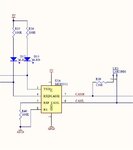
it should work - have you termination resistors on the CAN lines?
Can.jpg

what happens? using an oscilloscope can you see signals on the CAN lines?
do you have a UART connection to a PC so you can use printf() to see what is happening?

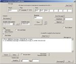
I find a CAN-USB device is useful for debugging CAN networks, e.g.
http://www.can232.com/
**broken link removed**
 

Hi FvM,

I had copied the CAN example code from microchip, but i confused about the code. How can i send the command or string? Can show me?
Code:
void CAN2RxMsgProcess(void)
{
	CANRxMessageBuffer * message;
	message = (CANRxMessageBuffer *)CANGetRxMessage(CAN2,CAN_CHANNEL3);
	if(message->data[0] == '1')
	{
          //take action
	}
	else
	{
            //take action
	}


    CANUpdateChannel(CAN2, CAN_CHANNEL3);
	CANEnableChannelEvent(CAN2, CAN_CHANNEL3, CAN_RX_CHANNEL_NOT_EMPTY, TRUE);
}

The data i received message->data[0] is 0. Is it the data i receive is correct?

- - - updated - -

Hi horace,

i had connect the resistor 120R between CAN_L and CAN_H.
When i observe the signal using the oscilloscope, the signal for CAN_L and CAN_H is high.
I had use UART for observe, as the code i write above, the message->data[0] i receive is 0.

Thank you^^
 
Last edited by a moderator:

Hi FvM,

I had copied the CAN example code from microchip, but i confused about the code. How can i send the command or string?
The data i received message->data[0] is 0. Is it the data i receive is correct?
looking at an earlier post your were setting the RTR bit and an RTR frame normally carries no message
e.g. I have sent two messages with ID 0xAAA first one normal frame with data )x1234567800000000 the second is an RTR frame
CANframe.jpg
 
Last edited:

Status
Not open for further replies.

Similar threads

Part and Inventory Search

Welcome to EDABoard.com

Sponsor

Back
Top