Continue to Site

Welcome to EDAboard.com

Welcome to our site! EDAboard.com is an international Electronics Discussion Forum focused on EDA software, circuits, schematics, books, theory, papers, asic, pld, 8051, DSP, Network, RF, Analog Design, PCB, Service Manuals... and a whole lot more! To participate you need to register. Registration is free. Click here to register now.

Relay Testing Circuit

Status
Not open for further replies.

Jester009

Newbie level 5
Joined
Aug 28, 2007
Messages
8
Helped
0
Reputation
0
Reaction score
0
Trophy points
1,281
Activity points
1,349
relay circuit

Hi,

I have been assigned to build a circuit to test overcurrent relays as my final year project. The simple idea is to send a current a current to the relay and measure the tripping time.

This is the first time I'm using the theories I learnt into action !
I have a basic plan. I would like to know if I'm taking the right path.

1. For the current injection circuit a H - Brigde is used.
2. Controlling the H - Brige is done by PIC 16F877
3. Software interface is done by Visual C#, so that the user can select the current to inject.

The thing is I don't have a clear idea about how to proceed. I would like to get schematics and resource material so that I can go forward. I have to complete the project within a month time. So any feedback is deeply appreciated!

Thanks in advance
Jester009
 

h bridge relay tutorial

what is the current range you want to design?
How are you planning to do it with H-bridge?
 

kcgg140 alsthom manual

Hi cameo_2007,

Thanks a lot for the reply. Initially I thought of making it for 10A. But have to go up to 75A.

Using a H-bridge is an idea only. What we planned was to use PIC's PWM output to drive the MOSfets in the H-Bridge.

If you have any other method to achieve this purpose please let me know....

Thanks again
Jester009
 

manufacture : alsthom+model: kcgg140

75A ??
Are you sure about the that rating.Looks quite heavy.
From where will you get a source to draw such currents.? do you have a transfromer?

I still didnt understand that how you are going with a H Bridge.And do you have that H-bridge with you.It costs you,sometimes more as you hav to procure just one or two numbers for your project.
 

test circuit diagram of relay

This is the bock diagram of the problem as I see it...
Code:
[I]**broken link removed**[/I] Layout.jpg

Code:
The H - Bridge comprised of MOSfets. Which are driven through a MOSfet driver. The PIC outputs two PWM signals which are being fed to the MOSfets. By changing the duty cycle of the PWM signals I can output a sinewave with different amplitudes.

This is the theory which is behind my plan. But please correct me if I'm wrong. I chose the H-Bridge for because I have seen it used for motor controlling applications.

Earlier I said that the output should be 75A. Pardon me I found out that the relay I'm gonna use require inly 10A max. So that won't be a problem.

I'm going to build the H-Bridge with four MOSfets. The MOSfets I'm using have a maximum drain current of 12A. So my output current will be 12A? To achieve an output current of 12A, what is the power rating of the supply to the H-bridge?

Please clear me on these matters...

Thanks
Jester009
 

kcgg 140

was that block diagram drawn by yourself?

H-bridge is normally used to control motors,especially dc motors.And yours is a relay,that just needs a current to be injected.PWM,the principle itself is meant for motor control applications,where the voltage amplitude,frequency etc are controlled.
And,in your case,its a relay,where you wanna control the current.
Frankly,tell me what made you to go ahead with an H-bridge,coz,me too curious to know,whether is there any technique like that,which i havnt come across?
here is a link about H-bridge:
http://www.mcmanis.com/chuck/robotics/tutorial/h-bridge/index.html
u could even google H-bridge,n understand the exact application of that and finalise whether you can use it for testing your relay.
 

relay testing procedure

Hi cameo_2007,

Seems I have done a grave error right at the beginning of the project. Actually the H-Bridge idea has been suggested by someone who said that my application is very similar to 'motor controlling'. So I went ahead with that in my mind. :?

But after reading about its applications I realized that its not been used for pure current controlling applications. But I'm getting the feeling that a half-bridge suites this purpose. Am I right?

Once again thanks a lot for your valuable input. This is the first time I'm building something. Can you please guide me to a direction where I can accomplice this task...

Thanks
Jester009

PS: I drew the block diagram. But I think it has not much use now...
 

injector pic 16f

Even a half bridge is not the ultimate one for your application.
Leave this 'bridge' concept.,if you really like that,change your project title to 'motor controlling'

on way is to use a triac for switching the relay.And control the triggering angle of the triac with the microcontroller.Insert a current transformer in tha path which fill give you a feedback of how much current is flowing,and transfer that data to the microcontroller again so that you have a control over the current.
hope you hav not gotten any clear picture.

but wait,whats the relay going to be tested.make? part number? type? do you have one in hand?
Only by looking into its characteristics and specifications,you can start designing/choosing the circuit.
 

kcgg 140 relay manual

I have to test a numerical overcurrent relay. These are the details...

Code:
Manufacture : ALSTHOM
Model: KCGG140

Nominal current 5A (CT secondary rating)
Auxiliary supply 24-125 DC

This is a bit old relay thats in our laboratory. Ammm yes I dont have a very clear picture about the circuit :?
 

kcgg140 current

tell me how that relay works?
exactly that particular relay what you have in hand.not in general.
what are its connections and to which terminalsare you planning to give the inputs etc.

A clear idea,before starting the project will make the circuit designing easier.Thats why i'm asking.
 

build overcurrent relay

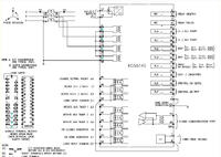
I have attached the terminal diagram of the relay.


1. Give supply from the injection circuit to 21-22 (Assuming only one phase is tested at a time)
2. Give auxiliary supply to 13-14 (24-125 DC)
3. Can get the tripping signal from 41-43

Nominal current of the relay is 5A. So the maximum current injected should be 5A...
 

Status
Not open for further replies.

Part and Inventory Search

Welcome to EDABoard.com

Sponsor

Back
Top