Continue to Site

Welcome to EDAboard.com

Welcome to our site! EDAboard.com is an international Electronics Discussion Forum focused on EDA software, circuits, schematics, books, theory, papers, asic, pld, 8051, DSP, Network, RF, Analog Design, PCB, Service Manuals... and a whole lot more! To participate you need to register. Registration is free. Click here to register now.

Relay Switch From Transistor

Status
Not open for further replies.

scmojks

Newbie level 5
Joined
Nov 14, 2012
Messages
8
Helped
0
Reputation
0
Reaction score
0
Trophy points
1,281
Activity points
1,352
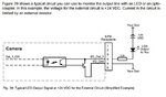
Attached is a section from a manual from an industrial camera.

The following is also a snippet from the manual:

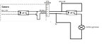
The camera is equipped with one physical output line designated as Output Line 1. The output line
is accessed via the 6-pin connector on the back of the camera.
The output line is opto-isolated.
recommended operating voltages. The absolute maximum voltage is +30.0 VDC. The maximum current allowed through the output circuit is 50 mA.
A low output signal from the camera results in a non-conducting Q1 transistor in the output circuit.


Voltage Significance
< +3.3 VDC The I/O output may operate erratically.
+3.3 to +24 VDC Recommended I/O output voltage.
+30.0 VDC Absolute maximum; the camera may be damaged, if the absolute maximum is exceeded.

A high output signal from the camera results in a conducting Q1 transistor in the output circuit.


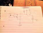
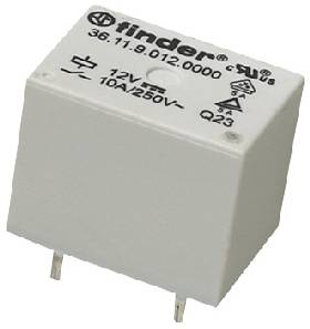
I want to switch a 24VDC relay coil with output line 1 and was wondering where do i connect A1 & A2 of the relay so that when the ouptut is turned on the relay will switch on,
Also if using a 24VDC 2.1 A do i need a resistor to limit the current in the circuit to 50mA to prevent damage to the camera?
i would intend to use a solid state relay

Any advise would be appreciated

Thanks
 

Attachments

  • cameraoutput.jpg
    cameraoutput.jpg
    46.8 KB · Views: 92

Hi scmojks
As i can see , the circuit has a big problem ! when optocoupler is on , the transistor can be destructed because you don't have any resistor in BE diode , path .
Best Wishes
Goldsmith
 

As i can see , the circuit has a big problem ! when optocoupler is on , the transistor can be destructed because you don't have any resistor in BE diode , path .
Best Wishes
Goldsmith

And where does the BE path diode current come from?
I think you should reconsider...

Alex
 

And where does the BE path diode current come from?
I think you should reconsider...
Hi Alex
Oops ! yeah . you're right . i didn't pay attention that , the path is low current ! very low current ! and i think it can't deliver large amount of current . but still i think adding a low value resistor e.g a 220 ohms would be better . isn't it ? ( i think that error is happened because today i just slept for two hours ! and i need to take a bit rest ! ;-) ( because i can't see anything , right now ! my eyes are going to be closed !! )
Regards
Goldsmith
 

Current diagram is ok, and works, LED uses 10mA, which exlude usage of low current led (2mA) with this resistor (2,2K).

You didnt show on diagram what is connected on Pins 1,2,3,6.

Relay also can be used on pins 4 and 5, but use low current relay 30-40mA, not some for car 150mA!!! In market you can search small sized and small current reed relays (5-10mA). Also if you want to protect internar output transistor in camera, use one additional optocoupler on 4 and 5 pins. Check specification for camera, they say max allowed current on 4 and 5 pins. You mention its 50mA max check that.

For me best solution is to use one additional optocoupler in serie with this LED.

Modified diagram :

cameraoutput.jpg

- - - Updated - - -

On output optocoupler transistor, use relay on standard way, resistor coil + diode. You can direct link relay coil on that transistor if relay is 30-40mA, for more stronger relays use one output transistor 2N2222A, BC546,....

For optocoupler you can use 4N27, 4N35,....
 
Last edited:

thanks

thanks i should have mentioned, i would not be switching the led shown in the attachment. The NO contact of the relay would be connected to a light drawing 2A
What i am trying to achieve- is when the output is turned on from the camera it closes the coil of the relay which fires on a light connected to the relay contacts (pin 11, 14 of the relay)


Below are the specs on the relay, i was intending to use a 24V 2A power supply. There is 12 Volts on pin 1 and pin 2 to power thet camera (but that is a different isolated circuit.

Also attached is a diagram on how someone advised me to set it up- they said to use a IN4007 diode across the relay. does that make sense?

SSR, 2A, 24VDC
Control Voltage Range: 16V DC to 30V DC
Operating Voltage Range: 1.5V DC to 24V DC
Contact Configuration: SPST-NO
Load Current: 2A
Relay Terminals: Through Hole
SVHC: No SVHC (19-Dec-2011)
Approval Category: UL Recognised
Control Current Typ: 7mA
Control Voltage DC Max: 24V
Control Voltage DC Min: 2V
Control Voltage Type: DC
External Depth: 5mm
External Length / Height: 15.5mm
External Width: 28mm
Input Impedance: 3200ohm
Input Voltage Max: 30V
Input Voltage Min: 16V
Isolation Voltage: 2.5kV
Load Current RMS Max: 20A
Load Voltage DC Max: 24V
Load Voltage DC Min: 1.5VDC
Load Voltage Range: 1.5V DC to 24V DC
Must Release Voltage: 10V
Operating Temperature Max: 55°C
Operating Temperature Min: -20°C
RMS Load Current Min: 2A
RMS Load Voltage Max: 24V
Series: 34
Terminal Type: Through Hole
 

Attachments

  • circuit.JPG
    circuit.JPG
    2.5 MB · Views: 77

Yes, use diode over relay (1n4007).

Use additional optocoupler to avoid overloading output transistor inside camera, just as on modified diagram in post#5. Add relay with diode to optocoupler transistor.

Relay with protection diode:
**broken link removed**


Use relays with smaller current of coil around 30-40mA. You can determine this based on coil resistance and working voltage (Ohm Law I=U/R).
 
Last edited:

Yes, use diode over relay (1n4007).

Use additional optocouplet to avoid overloading output transistor inside camera


.

sorry i dont quite follow this whats this optocouplet connected to?
 

Circuit in post #5 on additional optocoupler add relay and diode. That additional optocoupler allow you to use more current on output and avoid damage of optocoupler in camera.


Modified diagram:

cameraoutput.jpg
 
Last edited:

thanks but i wont have an LED in my circuit so does that mean i dont need the 2.2 K resistor?

I want the relay to turn on and switch a light connected to that relay can i use a 24V 2A supply?
 

thanks but i wont have an LED in my circuit so does that mean i dont need the 2.2 K resistor?

I want the relay to turn on and switch a light connected to that relay can i use a 24V 2A supply?

Diagram in post #9 turn Led and Relay On at the same time, when camera detect movement and turn outpun on. You need 2,2K resistor to limit LED current, just as diagram shows.
 

thanks but im not using an LED. The LED was shown by the manufactures as an example.

I want to switch an optocoupler with the output from the camera and have a 2A Light connected to the optocoupler


I.E camera output is on - my optocoupler comes on- then my light draws 2A from the 24V supply and switches on.
 
Last edited:

thanks but im not using an LED. The LED was shown by the manufactures as an example.

I want to switch an optocoupler with the output from the camera and have a 2A Light connected to the optocoupler


I.E camera output is on - my optocoupler comes on- then my light draws 2A from the 24V supply and switches on.


That light 1,5A connect on relay contacts. You can put 220V 1500W reflector on relay contacts (If relay can support that. Smaller relays can handle mainly 5A-10A on 220V).

Example:
12v-10a-relay.jpg
 

"You can put 220V 1500W reflector on relay contacts"

what this for?

These are the components i was trying to use

Camera cable- which has pin 4 & pin 5
24V DC 2A Power Supply
Light requires 24VDC 1A to function
Optocoupler specification on post 6


i dont understand what you are suggesting now
 

Then use 1A 24VDC for light on relay contact.

:smile:

Mercedes make cars for speed 300km/h but that dont mean that you must drive 300km/h.
 

Then use 1A 24VDC for light on relay contact.

:smile:

Mercedes make cars for speed 300km/h but that dont mean that you must drive 300km/h.

okay yes. can i wire up the circuit as shown
 

Attachments

  • testcircuit.jpg
    testcircuit.jpg
    30.8 KB · Views: 60

No, you cant.

Use circuit from post #9, remove LED diode and keep resistor 2,2K and optocoupler.

okay thanks i guess this is the circuit you are suggesting.

testcircuit2.jpg

would you mind explaining how the circuit works and what is the purpose of the resistor and how the optocoupler limits the current

thanks
 

Resistor limits current for led in optocoupler, max allowed continuous led current is 60mA for 4N35, that means that you can lower value of resistor if you want. Optocoupler transistor, for example 4N35, can drive continuous 100mA, and transistor in camera can drive 50mA (data from your first post). I think its better to protect internal parts in camera.


Best to see how this works use protoboard and all of thise parts, and see whats happening.
 
Last edited:

Status
Not open for further replies.

Similar threads

Part and Inventory Search

Welcome to EDABoard.com

Sponsor

Back
Top