Continue to Site

Welcome to EDAboard.com

Welcome to our site! EDAboard.com is an international Electronics Discussion Forum focused on EDA software, circuits, schematics, books, theory, papers, asic, pld, 8051, DSP, Network, RF, Analog Design, PCB, Service Manuals... and a whole lot more! To participate you need to register. Registration is free. Click here to register now.

[SOLVED] Relay Problem with AT89s52

Status
Not open for further replies.

torana

Member level 2
Joined
Sep 11, 2011
Messages
51
Helped
0
Reputation
0
Reaction score
0
Trophy points
1,286
Activity points
1,683
HII,

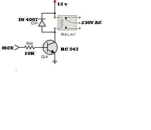
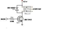
MY CONTROLLER IS AT89S52. I AM TRYING TO DRIVE 4 Nos RELAY.
transistor IS bc547.

WHEN EVER MY CONTROLLER IS GIVING HIGH PULSE TO BASE OF BC547 (THROUGH 10 RESISTOR),

THEN RELAY GETS OPERATE AND AUTOMATICALLY AGAIN IT CHANGE TO PREVIOUS CONDITION.

SOME TIME IT BECAME HANG. SO PLS HELP ME. THANK YOU


please give some more details
which port is used for driving the transistor base?
is your problem random or at a particular condition?
place one resistor in between emitter and ground and check the result.
 

please give some more details
which port is used for driving the transistor base?
is your problem random or at a particular condition?
place one resistor in between emitter and ground and check the result.

thank you...i am using port2 of at89s52. my problem is not at a particular condition. it is random.
 

First change Rb 10kohm resistors to 1 kohm
 

    V

    Points: 2
    Helpful Answer Positive Rating
Placing 10K between Emitter and Ground is not likely to work as the total current through the relay will then bee too small. Check the relay resistance, the required current and the transistor is capable of providing that. Also take care of the back emf from the relay winding connect a damping diode across relay winding. If the switching currents are also sizable attend to the spikes generated. This is most likely as the problem is not systematically repeating and is erratic.
 

What is the load your driving?
with out load is the system working ok
 

Atmel 89 series are Negetaive or GND favored chips. Thus they prefer gnd as inputs or they deliver GND or negetive as output too. Thus the posetive volatge what you get as output is not devilvered by the Chip. Its a voltage whiich is passing through the internal pullup resistor when the PIN floats. When activated the pin will pull itself to GND. Thus you may use a PNP transistor which will trigger the NPN transistor (Combination of two) OR use a NPN (Port <2K2> Base) Collector >10K> Vcc, Emitter > GND. Next NPN transistor Base > To First Tr collector, Emitter GND, Collector Relay as you have connected now.
Cheers
 

This can be done by darlington pair like TIP122
I have used it in my circuit to drive college bell relay, working fine.
 

If you have 12V relay then apply 18 volts because there is some voltage drop across collector to emitter.
 

instead of using an 10k resistor use this combination
8351712800_1352639761.jpg
 

Attachments

  • 86_1245521291.jpg
    86_1245521291.jpg
    43.3 KB · Views: 68

Status
Not open for further replies.

Similar threads

Part and Inventory Search

Welcome to EDABoard.com

Sponsor

Back
Top