Continue to Site

Welcome to EDAboard.com

Welcome to our site! EDAboard.com is an international Electronics Discussion Forum focused on EDA software, circuits, schematics, books, theory, papers, asic, pld, 8051, DSP, Network, RF, Analog Design, PCB, Service Manuals... and a whole lot more! To participate you need to register. Registration is free. Click here to register now.

Relay interfacing problem ,controller becomes reset

Status
Not open for further replies.
This new diagram is better.

On 5V for led put 2K its about 2mA for low current led.
On 12V low current led resistor for 2mA is 2,7K.

Put capacitors before 7805 100uF or 33uF and after 7805 pur 10uF and then 100nF.

Put 100nF on uC +/- pins closer to as possible.

And dont link AC with circuit !!!! AC dont have plus/minus, AC have neutral and phase. Only link AC wires on relay contacts, but pay attention on contacts not on coil.

---------- Post added at 14:14 ---------- Previous post was at 13:45 ----------

I must ask I dont see the purpose of led before 7805 and after, both led will light, what is purpose of thise two leds ?
 
Last edited:

If the relay is out of the circuit, does the microprocessor behave as it should without resetting?
 

Or he can try to put some led with resistor instead of relay, just for testing.

Also maybe he should check firmware of uC. First design of circuit is bad, we hope so that he improve that.
 
Last edited:

yes as tpetar said put an led and a resistor to check if it works fine! without a relay!
 

You want the device to turn on when pin 28 of the microprocessor is high, and turn off when it is low. Correct?
 

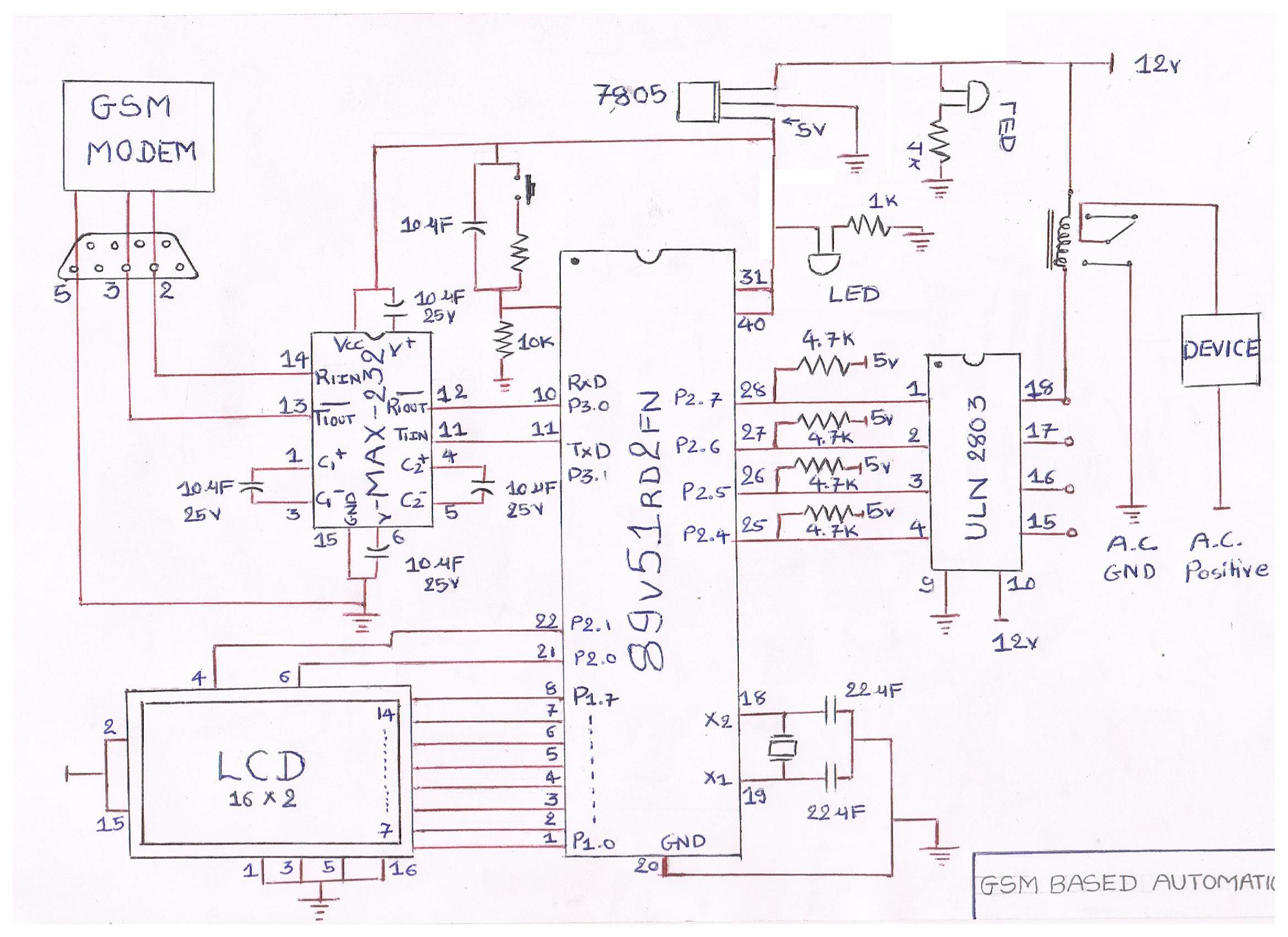
sorry for mistake this is my diagram (#22)

Now let us make it a bit better.

(1) As it was pointed out, you may like increasing the 1K (in series with the 12V LED) to save current. Now it is about 10mA. For 2K2, it will be about 4.5 mA... and so on. But this is not important.

(2) If your 12V is rather fixed and 7805 needs at most 7V to give 5V, we have 5V in excess that will heat the regulator. I use to add a resistor (Rs) between the regulator input and the supply 12V. To know the value of Rs, we need to know the maximum current (Is_max) that the regulator should supply (at 5V).
Rs (Kohm) =< ( 12V - 7V ) / ( Is_max + 5mA)
Ps_max = ( 12V - 7V ) * ( Is_max + 5mA)

In this case Rs will let 7805 dissipate less power.
And in case there is a short at the regulator input or output or it is defective, the highest current limited by Rs would be:
Is_short (mA) = 12V / Rs (Kohm)
Ps_short / Ps_max = [ 12V / ( 12V - 7V ) ] ^ 2 = 5.76 times
From the ratio 5.76, the resistor could be chosen to work fine for Ps_max and to burn for 5.76*Ps_max hence acting like a fuse to protect mainly the PCB tracks.

(3) Now it is important adding a capacitor (Cp) between ground (DC minus) and the node joining Rs and 7805 input. Its value should be relatively low to insure a fast rising at the 5V output which is necessary to reset properly the MCU at boot.
A typical value for Rs * Cp is 0.01 second (it is just a starting point since it is not critical).

(4) To ensure the stability of the regulator, I usually add at its output (and ground) two capacitors:
C1 = 100nF (low grade as ceramic is ok)
C2 = 2.2uF to 10uF
In any case, Cp > C2 to avoid a reverse polarity on the regulator when the power is off. If the discharge rate of C2 should be lower than Cp, a protecting diode from output to input of 7805 will protect it.

Note:
To measure Is_max, you can place (as a test) Rs=10 Ohm and measure its voltage (Vs) when the circuit is active.
Is (mA) = Vs / 0.01

Finally, I hope you can find a relay in which its DC and AC sides are better isolated/seperated (surely not like the one you posted earlier).
And adding the R+C (like 500mW 150R, and 10n/630V) at the relay AC terminals will eliminate the spikes that reset your MCU.

Kerim
 
Last edited:

Hello prasant
Really u will not finish this problem until u do what we say and answer our questions.
1)did u remove the led and 1k resistor i asked u ?
2)did u check there is no connection between the ac grd and all other grd?
3) did u after doing "1" that u have 5v between low voltage grd/12v return (middle pin of reg 7805) to pin 31 & pin 41?
4) check for resisatance between 2 of the 5 pins (those r the coil leads)and tell us what u found next check for nearly zero ohm between the rest of the 3 pins and post results.
5)7805 is it metal with a hole or plastic... if metal check for zero volts between metal to pin 20 mcu...recheck the relay after u found out the coil lead earlier that from those leads 1 of them is really going to +12v and other to uln pin 18 .
6) check for 12v to reg input with ref to return... check for zero ohm and zero volt between pin 9 uln and return...check for 5v stable between return and reg output and pins 31 40 mcu.
read my post #8 and tell me if u understand all of it and if u have done all i said ... and what u had before and what u did after my #8 post
good luck
 

It is the old story. Once a circuit has been built, get the volt meter out and check supply voltage and the various components input and output voltages.
 

That's electronics
get to it a start working u will get great experience and great satisfaction and knowledge once it works.
who built this circuit and when ?
 

Status
Not open for further replies.

Part and Inventory Search

Welcome to EDABoard.com

Sponsor

Back
Top