milind.a.kulkarni
Advanced Member level 3
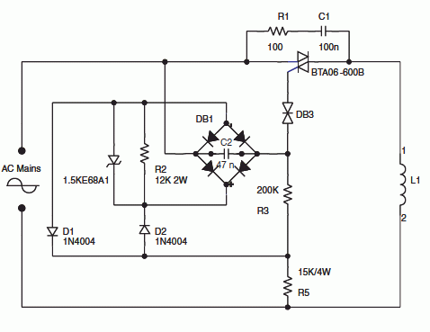
How to use transformer of 240/12v 1 amp on 440v on primary using resistors , what are design consideration for selection of the resistors? Is there is any circuit that is recommended? Please guide me.
Follow along with the video below to see how to install our site as a web app on your home screen.
Note: This feature may not be available in some browsers.
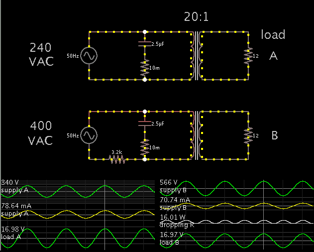
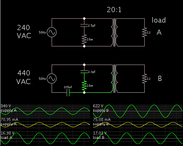
Apparently you assumed an unrealistic high magnetizing current in the simulation (cos phi at rated load < 0.3 !).One thing that helps a lot is a capacitor across the primary, for power factor correction. It greatly reduces current draw.
Apparently you assumed an unrealistic high magnetizing current in the simulation (cos phi at rated load < 0.3 !).
Apparently you assumed an unrealistic high magnetizing current in the simulation (cos phi at rated load < 0.3 !).
A point that hasn't been said yet, is the 12V/1A load expected permanently with no risk of disconnection? Otherwise the transformer would be burned in the voltage divider circuit.