Continue to Site

Welcome to EDAboard.com

Welcome to our site! EDAboard.com is an international Electronics Discussion Forum focused on EDA software, circuits, schematics, books, theory, papers, asic, pld, 8051, DSP, Network, RF, Analog Design, PCB, Service Manuals... and a whole lot more! To participate you need to register. Registration is free. Click here to register now.

[SOLVED] regarding ldr sensor....

Status
Not open for further replies.

PRABAKARDEVA

Full Member level 2
Full Member level 2
Joined
Sep 16, 2013
Messages
127
Helped
2
Reputation
4
Reaction score
2
Trophy points
1,298
Location
Chennai
Visit site
Activity points
2,168
i had written the adc coding...but i couldn't get the output for ldr sensor.....i couldn't find the flaws in coding....can anyone help?
 

Code:
int main(void) {
    TRISD = 0x00;

    PORTD = 0x00;
    //adc initialize
    adc_init();
    unsigned int ldr_val;

    while (1) {
        // read channel 0
        ldr_val = adc_read(0);
        ldr_val /= 10;
         if (ldr_val > 50)
            PORTD = 0xFF;
        else
            PORTD = 0x00;
    }
    return (1);
}
 

hi

i am not familiar in pic. but generally, i will give some points, i hope you had correct initialization in adc code and no hard ware faults. first thing is, check the ref voltage of the micro-controller ,
second thing is, check the datatype of the ldr_val
 

hi

i am not familiar in pic. but generally, i will give some points, i hope you had correct initialization in adc code and no hard ware faults. first thing is, check the ref voltage of the micro-controller ,
second thing is, check the datatype of the ldr_val


what is fault in datatype?
 

hi

i didnt see the data type of the ldr_val before, now i saw that , i thing , the output of the ADC in pic 10 bits resolution. so unsigned int is enough.
 

TRISx is not set for ADC pin. ANSEx, ADCONx, CMCON, CM1CON0, CM2CON0, VRCON, CVRCON, registers if exists is not configured. LDR circuit o/p voltage range is not mentioned. uC and Fosc is not mentioned. Post Circuit and mikroC project files zipped.
 

TRISx is not set for ADC pin. ANSEx, ADCONx, CMCON, CM1CON0, CM2CON0, VRCON, CVRCON, registers if exists is not configured. LDR circuit o/p voltage range is not mentioned. uC and Fosc is not mentioned. Post Circuit and mikroC project files zipped.
hi jayanth.....i had just posted my main file.....i had written driver file for the adc_init() which done the everything.fosc and uc mentioned in compiler.....posted that code for your verification.
 

HTML:
void adc_init(void)
{
	ADRESH=0;
	ADRESL=0;
	RA0=0;
	TRISA0=1;
	ADCON0=0x81;
	ADCON1=0xCE;
	}
	int adc_read(unsigned char channel)
	{
		unsigned char lsb,msb;
		unsigned char result;
	ADCON0 &= ~(0x07 << 3);         
    ADCON0 |= (channel<< 3);
    __delay_ms(1);
    ADON=1;
		GO_DONE=1;
		while(GO_DONE)
		{
			;
			}
			lsb=ADRESL;
			msb=ADRESH;
			result=(msb>>8)+lsb;
			return result;
			}


may i change need to change anything?
 

I hope msb and lsb are 8 bit variables, result is 16 bit variable and left justified is used for ADC result. So, use


Code C - [expand]
1
result = (msb << 8) + lsb;


or


Code C - [expand]
1
result = (msb << 8) | lsb;


ADCON0 value is wrong. Mention Fosc used and show how you calculated Tad.
 
Last edited:

i had tried that justification..but i couldn't get the output.....actually i was trying to see the result of the adc by using lcd.....i got the output '24'.i don't know..how i got?
 

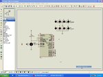
cxaaa.jpg


fosc 1s 20mhz
 

Circuit is ok. You need resistors for LEDs in real circuit. Calculate Tad for 20 MHz and set ADCS0-ADCS2 accordingly.

Remove these


Code C - [expand]
1
2
ADCON0 &= ~(0x07 << 3);         
ADCON0 |= (channel<< 3);


Use these values


Code C - [expand]
1
2
ADCON0=0x81;
ADCON1=0x8E;

 
Last edited:

Status
Not open for further replies.

Similar threads

Part and Inventory Search

Welcome to EDABoard.com

Sponsor

Back
Top