sabu31
Advanced Member level 1
Hi All,
I wanted to know what is the difference in electric field in these two configurations. The purpose is to design electrodes for non-thermal processing of liquid using Pulsed Electric Field (PEF) Technique where the typical field required is 30kV/cm to 50kV/cm. Typically parallel plate configuration and coaxial configuration is used. I have seen that some papers mentioned typical load is around 200 Ohms -1000 Ohms. I am attaching two configurations,
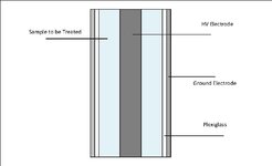
Configuration 1 : High Voltage Inner Electrode (Stainless steel), Surrounded by Plexiglass, which is finally surrounded by ground electrode (SS)
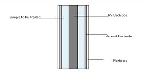
Configuration 2 : High Voltage Inner Electrode (Stainless steel) which is finally surrounded by ground electrode (SS), Surrounded by Plexiglass
In configuration 1, there is very little current drawn (load is typically 10kOhm), but in configuration 2 the current is very high (say typically 40ohm load). The pulse applied is 10us width and 250Hz.
Its mentioned in literature that the process is of microbial inactivation is due to high field.
Is the field same in both cases? Which configuration is typically used.
A sample reference for the PEF is
S. H. Jayaram, "Pulsed Power Applied to Process Industry," in IEEE Industry Applications Magazine, vol. 16, no. 4, pp. 34-40, July-Aug. 2010, doi: 10.1109/MIAS.2010.936968.
I wanted to know what is the difference in electric field in these two configurations. The purpose is to design electrodes for non-thermal processing of liquid using Pulsed Electric Field (PEF) Technique where the typical field required is 30kV/cm to 50kV/cm. Typically parallel plate configuration and coaxial configuration is used. I have seen that some papers mentioned typical load is around 200 Ohms -1000 Ohms. I am attaching two configurations,
Configuration 1 : High Voltage Inner Electrode (Stainless steel), Surrounded by Plexiglass, which is finally surrounded by ground electrode (SS)
Configuration 2 : High Voltage Inner Electrode (Stainless steel) which is finally surrounded by ground electrode (SS), Surrounded by Plexiglass
In configuration 1, there is very little current drawn (load is typically 10kOhm), but in configuration 2 the current is very high (say typically 40ohm load). The pulse applied is 10us width and 250Hz.
Its mentioned in literature that the process is of microbial inactivation is due to high field.
Is the field same in both cases? Which configuration is typically used.
A sample reference for the PEF is
S. H. Jayaram, "Pulsed Power Applied to Process Industry," in IEEE Industry Applications Magazine, vol. 16, no. 4, pp. 34-40, July-Aug. 2010, doi: 10.1109/MIAS.2010.936968.