rxb
Newbie level 5
Hello all.
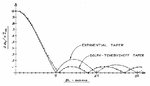
I am working on designing a transmission line which involves the use of a taper. One of the issues I am struggling to understand conceptually is this reflection coefficient often shown for your standard exponential, Klopfenstein, hyperbolic tapers like the one attached to this post.
So what does not make sense to me here is the low frequency behavior shown in that image. I thought you only had to worry about impedance mismatching/control for higher frequencies. At DC-Low frequency the only thing of concern should be resistivity no? What I mean to say is if I attached one end of the taper to a dc/low freq power supply and the other end to a 50 ohms terminator and measured the voltage across the terminator, I should just get a voltage divider no?
So I guess my question is how am I supposed to interpret that graph? At high frequencies it makes sense to me, because losses and reflections are governed by the characteristic impedance where ωL>>R. But I'm not sure what it means at low frequencies, is it really a high pass filter? If not at what point does impedance begin to dominate? I've read some places that impedance control only really becomes important when the trace approaches λ/8.