Continue to Site

Welcome to EDAboard.com

Welcome to our site! EDAboard.com is an international Electronics Discussion Forum focused on EDA software, circuits, schematics, books, theory, papers, asic, pld, 8051, DSP, Network, RF, Analog Design, PCB, Service Manuals... and a whole lot more! To participate you need to register. Registration is free. Click here to register now.

reflectarray interested

Status
Not open for further replies.
hi abdoeng..
can i simulate plane wave and waveguide simultaneously in cst?
 

Thanks for reply,

yes... i mean the fixed directed beam. So how do you change the beam direction?

Let say if we have a center feed horn illuminate the reflectarray from top, and the reflected field should form a beam on theta= 0 degree. So if we want to make the beam point to theta = 30 degree away from broadside direction, so how can i do this?

Any suggestion will be appreciate. :)
Thanks
 

hi abdoeng..
can i simulate plane wave and waveguide simultaneously in cst?

sure
floquet mode and waveguide are same exactly result as thi=phi=0
but floquet is more general

---------- Post added at 21:56 ---------- Previous post was at 21:49 ----------

Thanks for reply,

yes... i mean the fixed directed beam. So how do you change the beam direction?

Let say if we have a center feed horn illuminate the reflectarray from top, and the reflected field should form a beam on theta= 0 degree. So if we want to make the beam point to theta = 30 degree away from broadside direction, so how can i do this?

Any suggestion will be appreciate. :)
Thanks

so easy
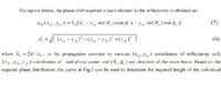
just change theta node=30 instead of zero in that equation of how we get the phase (reflectarray principle)
 
Thanks for the useful equation for phase distribution, you are so kind.
 

I have simulated a number of configurations for unit cell element and used boundary conditions to represent infinite reflectarrays. untill now I was only simulating for reflection loss and reflection phase performance, Now I want to do obtain the Farfield patterns. Can You please help me to generate Farfield patterns using CST or HFSS.? ONe of my designed model is attached.
 

Attachments

  • Radiation pattern test teflon.rar
    13.8 KB · Views: 155

I have simulated a number of configurations for unit cell element and used boundary conditions to represent infinite reflectarrays. untill now I was only simulating for reflection loss and reflection phase performance, Now I want to do obtain the Farfield patterns. Can You please help me to generate Farfield patterns using CST or HFSS.? ONe of my designed model is attached.

just add in a farfield monitor and simulate it, then you will get the farfield pattern. Or you means other things?

---------- Post added at 01:58 ---------- Previous post was at 01:47 ----------

floquet mode and waveguide are same exactly result as thi=phi=0
but floquet is more general

Hi abdoeng,

Do you mind to explain what is "thi=phi=0" representing? and if i use waveguide method, when simulate the complete reflectarray, what inter-element spacing i should use?

Thank you
 

Thanx Amanda for your reply.
I have already got the farfield in CST MWS by using periodic boundaries and then defining a finite reflectarray in the farfield options.
Just by adding the farfield monitor does not work as we have to define appropriate boundary conditions..
 
  • Like
Reactions: panou

    panou

    Points: 2
    Helpful Answer Positive Rating
Thanx Amanda for your reply.
I have already got the farfield in CST MWS by using periodic boundaries and then defining a finite reflectarray in the farfield options.
Just by adding the farfield monitor does not work as we have to define appropriate boundary conditions..

Hi konmpy,

Good to hear that you got the farfield.
By the way, why you want to know the farfield pattern of the single element?
 

Reflectarray Farfield pattern

Hi Amanda,
Actually I am not interested in the farfield pattern of single element. However I am simulating a single element and with the help of boundary conditions I am looking for the Farfield pattern of an array where I can vary the number of elements in order to observe the effects on Farfield pattern.
 

Re: Reflectarray Farfield pattern

no konmpy
u wrong
each element have its schematic and its sizes so they all not same in shape ,i.e. each one have its unique farfield so it wrong to assume u get the farfield of one element and multiply it by array factor to get the reflectarray total far field

---------- Post added at 15:55 ---------- Previous post was at 15:54 ----------

i think i reply to u shahzad
i hope my reply help u
 
hey hi...My minor project was based on reflectarray antenna using microstrip patches..
 

what kind of help need krishna?
 

Hey I am not getting the desired output...can u plz send me a simple simulation of reflectarray antenna...!!
 

yes,i use 2009 CST in simulation

Hi Abdoeng.

I have tried to simulate reflectarray antenna based on FSS unit cell with HFSS-IE. It takes long time..... and need huge of RAM.
Do you suggest simulation of reflectarray using CST? Do you have any example in CST to send it to me? It can help...

Thanks
 

Sure
CST more faster and efficiently for large array
i also recommend CST microstripes,it also very fast
 

Sure
CST more faster and efficiently for large array
i also recommend CST microstripes,it also very fast

Thanks abdoeng,

Do you have any example file to share with me? It can help....

Thanks
 
Thanks abdoeng,

Do you have any example file to share with me? It can help....

Thanks
If you search about my comment about reflectarray,u will find some files i already uploading them
regards
 

hello abdoeng, have u simulation file about reflectarray antenna? can you send it to me? because i am elementry.
 

if u need cell file simulation,may i upload it
 

hi
i have problem with reflect array model in hfss really i want to extract the phase reflection by theta
 

Status
Not open for further replies.

Part and Inventory Search

Welcome to EDABoard.com

Sponsor

Back
Top