Continue to Site

Welcome to EDAboard.com

Welcome to our site! EDAboard.com is an international Electronics Discussion Forum focused on EDA software, circuits, schematics, books, theory, papers, asic, pld, 8051, DSP, Network, RF, Analog Design, PCB, Service Manuals... and a whole lot more! To participate you need to register. Registration is free. Click here to register now.

Reed switch CR measurement circuit

Status
Not open for further replies.

freemanantony

Member level 4
Joined
May 19, 2010
Messages
70
Helped
0
Reputation
0
Reaction score
0
Trophy points
1,286
Location
Chennai, India
Activity points
2,005
Hello every body,
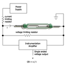
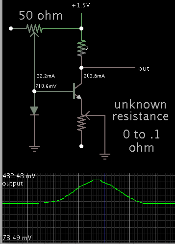
i am doing a project for testing reed switches. For measuring Contact Resistance of Reed Switch i am using the circuit which is attached with this post. But with this circuit hardly i can differentiate between 48 milliohms and 36millohms because the measured voltage when Switch is closed is too close to differentiate . So does anyone know any other circuit so this problem can be avoided
 

Attachments

  • drawing_cr_circuit.png
    drawing_cr_circuit.png
    18.4 KB · Views: 107

hi,
You could consider using a modified half or full Wheatstone bridge to drive into the IA amp.

E
 

You get mV voltage drop at decent current levels. Where's the problem?

Any industry standard milliohm meter can measure the resistance rather accurately.
 

just a suggestion

you need a constant current generator.
then the reed switch resistance = vreed/I. (I constant @ 1A say)
one can either have a high measuring voltage and a large resistor value.
(not safe), or make a constant current generator using a fet.
 

A transistor amplifier in common-base operation will give you a range of a few tenths of a volt.

Simulation:

3415444200_1408734747.png


The potentiometer was dialed from zero to .1 ohm, then back.

The bias needs to be low impedance. To adjust it will be tricky. If you're not careful, one slip will fry the transistor.

yeah that's a good idea but turn the diode up the other way
make it a zener increase the supply to 12V, make the emiter
resistor = zener voltage-vbe /desired test current, (or you can use a pot), put the reed switch
in the collector use a dvm to measure the voltage across the reed, its the standard way. or an adc or a meter.
if test current=100ma its a direct reading no calculation
required. a fet used as a current source would be better.
 

When testing any component, it is advisable to use the same test parameters used by the manufacturer, in this case , static and dynamic resistance for a standard current such as 10mA. As temperature rise , capacitive load and surge current all accelerate the rise in initial resistance, these must be factored in obtaining reliability results.

There will be failures due to coil and mechanical forces and others due to material quality and design contact area that affect results.

I am not sure if you are qualifying a part or trying to test it for aging or what but 10mA with an ADC gain- effective resolution of 0.01mV with 1uV of noise will yield an effective resolution of 1 milliohm easily with averaging or integrate and dump type .

Null offset calibration is necessary.

If the part is spec'd at 0.1 ohm, then wide variation as much as 30-50 mOhm can be expected, until a thin oxide is burnt off.
 

Status
Not open for further replies.

Part and Inventory Search

Welcome to EDABoard.com

Sponsor

Back
Top