Continue to Site

Welcome to EDAboard.com

Welcome to our site! EDAboard.com is an international Electronics Discussion Forum focused on EDA software, circuits, schematics, books, theory, papers, asic, pld, 8051, DSP, Network, RF, Analog Design, PCB, Service Manuals... and a whole lot more! To participate you need to register. Registration is free. Click here to register now.

Reducing via drill hole on OrCAD Layout

Status
Not open for further replies.

cerilet

Newbie level 4
Joined
Mar 16, 2011
Messages
5
Helped
0
Reputation
0
Reaction score
0
Trophy points
1,281
Location
Valencia
Activity points
1,309
Hi everyone,

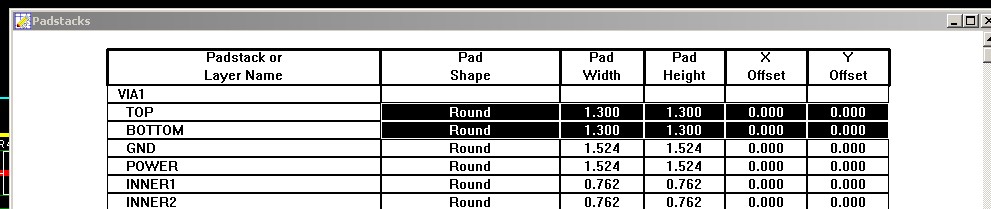
I am trying to print a board which has 0.2mm via drill holes, but when I print the top and bottom with the selection box Keep drill holes open checked the drills are bigger (0.8mm aprox.). I can not print them less than this value.

How can I fix it?

I am using OrCAD 16.2.0.

Thanks so much.
 

Check the padstack spreadsheet for the correct drill details!

The normal via drill given is 0.5mm and above!
 

Yes I did it in that way but doesn't works. I select the VIA1 and change the drill but nothing. I think is something wrong with the printing.

When I used OrCAD Layout 9 it worked, but with newer versions not.

Thanks for answering!
 

Check if there are more than 1 via type in the layout.

Right click on via - change via
 

In my design via1 is only used. All others are undefined (all set to zero).
 

Click the "View Spreadshheet" button and select "Padstaks'. Edit the via comform design.
Good look.
 

I did it in this way. I think OrCAD has a programming error.

I tried all possible solutions but nothing.
 

Status
Not open for further replies.

Part and Inventory Search

Welcome to EDABoard.com

Sponsor

Back
Top