Continue to Site

Welcome to EDAboard.com

Welcome to our site! EDAboard.com is an international Electronics Discussion Forum focused on EDA software, circuits, schematics, books, theory, papers, asic, pld, 8051, DSP, Network, RF, Analog Design, PCB, Service Manuals... and a whole lot more! To participate you need to register. Registration is free. Click here to register now.

Reducing Ripple Voltage w/o Capacitance

Status
Not open for further replies.

turtlepokerman

Junior Member level 2
Joined
Nov 8, 2012
Messages
21
Helped
0
Reputation
0
Reaction score
0
Trophy points
1,281
Visit site
Activity points
1,463
Good Afternoon Everyone,

I am currently working on building a high current lithium-ion battery charger and was wondering if there would be anyway to reduce ripple voltage from a full-wave rectifier without adding additional capacitance. At the current specs of 108V and 14 Amps, the circuit requires a ridiculous amount of capacitance (~2.3F) to smooth the ripple. This will of course be extremely expensive to implement. This DC voltage will then be stepped down by a buck converter. Does anyone know of a good trick to remove the ripple voltage without large amounts of capacitance?

Thanks for the help!
 

At the current specs of 108V and 14 Amps, the circuit requires a ridiculous amount of capacitance (~2.3F) to smooth the ripple.
Why? 5000uF would only give about 25V pk-pk ripple. Surely the buck converter can cope with that?
 

If the rectifier is followed by a buck converter, then input ripple should be rejected by the control loop of the buck, so long as Vin>Vout. If Vin>Vout requires very low input ripple, then you should probably look at another converter topology which doesn't have that limitation.
 

The problem is that Lithium-Ion batteries have a extremely low voltage swing tolerance. I am looking at a Vpp of 50mV. This is why I need to greatly reduce the ripple voltage.
 

The problem is that Lithium-Ion batteries have a extremely low voltage swing tolerance. I am looking at a Vpp of 50mV. This is why I need to greatly reduce the ripple voltage.
Wait, are the batteries being charged directly from the rectifier, or from the buck converter?? You should post some kind of schematic or diagram to clarify...
 

Here is the general layout of the schematic:

Circuit_Schematic.JPG
 

Here is the general layout of the schematic
It confirms godfreyls assumption in post #2. The buck converter can remove the ripple.

In most countries, power quality regulations require a PFC input stage.
 
Do you know of any text that could help me design a PFC input stage (Assumming that means Power Factor Correction)?
 

Here is the general layout of the schematic:

View attachment 88050
Okay as we've said, the buck converter should reject practically all input ripple via a feedback loop. Any ripple signal that does make it across the buck converter to the battery should be insignificant to the high frequency ripple created by the buck converter itself.

As for the input filter capacitors, they need only meet these specs:
1) Tolerate the combined ripple currents from the rectifier and buck converter
2) Meet required holdup times under max load and minimum input voltage

Many control chip manufacturers make good literature explaining PFC. Look at white papers and app notes from Texas Instruments, Intersil, International Rectifier, Linear Tech, etc.
 
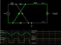
A choke is an alternative (or an assist) to capacitors.

This simulation shows (theoretically) that a value of 1/3 Henry will reduce ripple to 5%, when carrying 14 A of rectified mains AC.


I can't say whether a choke will be cheaper than a 2.3 Farad capacitor bank rated for 108 VDC.

The simulation shows a squarish current waveform, not a sine wave, being drawn from the supply.
Although it does not show any power factor phase change, I can't say how much of a problem that will be.
 

Status
Not open for further replies.

Part and Inventory Search

Welcome to EDABoard.com

Sponsor

Back
Top