Continue to Site

Welcome to EDAboard.com

Welcome to our site! EDAboard.com is an international Electronics Discussion Forum focused on EDA software, circuits, schematics, books, theory, papers, asic, pld, 8051, DSP, Network, RF, Analog Design, PCB, Service Manuals... and a whole lot more! To participate you need to register. Registration is free. Click here to register now.

Reduce Current on a 12V Pump

Status
Not open for further replies.

ryanturner

Newbie level 4
Joined
Feb 4, 2012
Messages
6
Helped
0
Reputation
0
Reaction score
0
Trophy points
1,281
Activity points
1,333
Hello,
As you can see this is my first post, so ill try and be brief.
Basically i have a kayak with a 12V 7A battery fitted, also fitted a fishfinder that draws 0.15A an hour. This gives me plenty of time when at sea.

I have just fitted a live bait well with a water pump that draws 2.5A an hour. As you can see this wont last long on my battery so i was wondering if i can put a circuit in to reduce the Current, saving my battery, or better still design a logic circuit to lets say, turn it on for 2 mins, every 10 mins.

I have actually just started an electric/tronic apprentiship so have a bit of knowledge in logic etc.

If any one could provide me with a starting block that would be amazing! thanks i advance for any replies.
 

ahh yes, of course, thanks for that. Ive built these before for other small apps such as flashing led's. I will get at building it now then... you may hear from me again yet though, thanks for your help.
 

More details about timers using 555 circuit here:
**broken link removed**

Meanwhile, look at this diagram:
 

Attachments

  • 555 timer v2.GIF
    555 timer v2.GIF
    18.6 KB · Views: 98

:lol:
Let's try to modify the first diagram in order to achieve correct duty cycle...
 

Attachments

  • 555 timer v3.GIF
    555 timer v3.GIF
    15.4 KB · Views: 107
Thank you for that diagram, i guess youve done the hard work for me there, thanks. so thats what i need to make the circuit go on for about 2 mins and off for 8-10 mins? This should save alot of battery power, thanks.

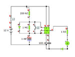
I did start to try get my head round things and built this with a motor as an output. Would this not work? seems rather basic but i worked out tm=0.7x200kx1mF=140s ON and ts=0.7x1Mx1mF=700s OFF. Also like the idea of being able to give it a 'boost' by pressing the push to make switch, resetting the cycle, starting from on for another 140s

Untitled-1 copy.jpg
 
Last edited:

Yes, in theory that’s correct but in practice the 555 circuit output can’t give you too much current to drive directly the motor. Also there’s a need to use some protection diode (when power is cut the diode is supposed to re-route the voltage/current from the coil/motor back onto itself, so the magnetic field energy is dissipated from the coils own electrical resistance).
 
Sorry to bother you again, I cant seem to get the circuit you gave me going on croc tech, maybe im connecting the relay wrong.

On that circuit i drew, can i not connect a MOSFET from the output of the 555 into the gate, the motor inbetween drain and power then source to ground. I dont know much about this component so will this get me enough current... what value should i aim for?

thanks for your patience with idiots like me!
 

Yes, that's the same diagram for using a bipolar transistor.
 

Attachments

  • 555 NMOSFET.GIF
    555 NMOSFET.GIF
    26 KB · Views: 97

Status
Not open for further replies.

Part and Inventory Search

Welcome to EDABoard.com

Sponsor

Back
Top