Driverterminator
Newbie
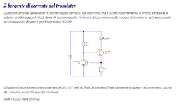
Hi guys, i'm new. My name is Aldo and as my 1th post I want to show you an interesting argoment that can teach you how to make a laser driver compatible for any type of laser diode... You just have to change the resistor actoss R2 to set output current: https://www.merghart.com/p/27/Two-Transistor-laser-current-source
So today i'm trying to test if this driver is working, and i've seen a youtuber making the same circuit, but he is using 2 PNP transistors instead 2 NPN... Anyway the circuit is the same and it's cleary visible at the second 00:00:50 see the following video here:
What i can't understand is: why he added 2 capacitors (which are not included on the drawn scheme)??? See minute 00:01:50 ???
NOW I HAVE 2 SERIUS PROBLEMS:
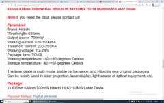
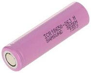
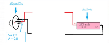
1) I need to run a red laser that has a drop around 2.3-2.7 volt at 0,82 A, and i want to use """A SINGLE CELL""" (Li-ion 3,7... 18650 battery size). (see my attached files). The reason is because i don't have much space for my project... I want to make a compact laser using a simple flashlight... so i must reduce the space and use 1 single cell.
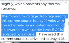
NOTE = I don't want to use 2 RCR because i want it can endure more with a 18650. So please understand my point... What i'm trying to do is to make this driver more effective... So i'm trying to make the dropout, """lower" than 1,1 volt, and as the post said, """it is cleary possible to reduce the voltage drop by using a simple mosfet...""" The problem is that i don't know wich mosfet is the best for my laser diode and i don't know where to connect to this circuit. So i don't even know which is the formula used if i substitute the Transistor Q2 with a mosfet.
2) The second problem is that since the guy on this video added 2 capacitors i started to have a lot of doubth about.. (i must add more components)... And now, I don't know where to connect these 2 capacitors to this simple circuit, and i don't know even the value of these 2 capacitors.
-------------------------------------------------------------------------------------------------------------
Now, could you help me by drawing the circuit and show me cleary how to use the mosfet instead the BJT and where to add these 2 capacitors please? I'm getting crazy and no one help me
Thanks you.
So today i'm trying to test if this driver is working, and i've seen a youtuber making the same circuit, but he is using 2 PNP transistors instead 2 NPN... Anyway the circuit is the same and it's cleary visible at the second 00:00:50 see the following video here:
What i can't understand is: why he added 2 capacitors (which are not included on the drawn scheme)??? See minute 00:01:50 ???
NOW I HAVE 2 SERIUS PROBLEMS:
1) I need to run a red laser that has a drop around 2.3-2.7 volt at 0,82 A, and i want to use """A SINGLE CELL""" (Li-ion 3,7... 18650 battery size). (see my attached files). The reason is because i don't have much space for my project... I want to make a compact laser using a simple flashlight... so i must reduce the space and use 1 single cell.
NOTE = I don't want to use 2 RCR because i want it can endure more with a 18650. So please understand my point... What i'm trying to do is to make this driver more effective... So i'm trying to make the dropout, """lower" than 1,1 volt, and as the post said, """it is cleary possible to reduce the voltage drop by using a simple mosfet...""" The problem is that i don't know wich mosfet is the best for my laser diode and i don't know where to connect to this circuit. So i don't even know which is the formula used if i substitute the Transistor Q2 with a mosfet.
2) The second problem is that since the guy on this video added 2 capacitors i started to have a lot of doubth about.. (i must add more components)... And now, I don't know where to connect these 2 capacitors to this simple circuit, and i don't know even the value of these 2 capacitors.
-------------------------------------------------------------------------------------------------------------
Now, could you help me by drawing the circuit and show me cleary how to use the mosfet instead the BJT and where to add these 2 capacitors please? I'm getting crazy and no one help me
Thanks you.